DATARECOVERYUNION.COM

USB Flash Drives – Instant Storage

Alternate Names: USB flash drives | USB keys | USB memory stick | USB sticks | Flash Drives | Jump Drives | Key Drives | Pen Drives | Thumb drives

What is the hottest back-to-school item this year? So red-hot that Mom and Dad will see it and want it too? It’s a tiny portable data storage device that plugs into the computer’s USB (Universal Serial Bus) port. Just a few of the brand names explain what it is. Here are some examples: TravelDrive™ from Memorex, Mini Cruzer™ from Sandisk, JumpDrive™ from Lexar. These small, pocket-sized storage devices are easy to work with, can plug in to any type of computer that is less than 8 years old or that has a USB port.

The great thing is that USB flash drives are really affordable now and for less than $100 you can get a 1GB USB storage device. Although flash drives have many uses, a common one is for transferring files from your work computer to your home computer, eliminating the need for lugging a laptop back and forth. (Although these devices go by many names, for purposes of this article, we will use the term flash drive.)

This article will take a look at this micro-technology, its history and future; you’ll be surprised to find out how prevalent this technology is and how long it has been around. As always, we will take a look at recovery options for these devices.

Flash Drives
In order to better understand the flash devices we have now, let’s take a moment and look at their history. Rudimentary flash memory began as integrated circuit chips that would come to be a standard in all electronic devices. These were known as CMOS (Complementary Metal-Oxide-Semiconductor, pronounced ‘see-moss’) circuits. These small, low power, high-density circuits could be designed to perform a variety of functions and operations. Initially designed in 1963 and first produced in 1968, these little chips were the beginning of the digital integrated circuit. Perhaps you had a computer 17 years ago and remember the importance of the CMOS chip; the CMOS chip controlled the basic system settings and is similar to the BIOS (Basic Input/Output System) on today’s computers.

CMOS integrated chips were a fantastic innovation; however, they were vulnerable to electro-static discharge, had to be handled carefully, and these chips always needed a constant power source to maintain the data. Did you ever have to replace the CMOS battery on your 8088 or 8086 computer? Then you remember that once the power was gone, you had to re-enter all of your computer’s settings.
A new style of chip called EEPROM (Electrically Erasable Programmable ROM or Read Only Memory) was the successor to the CMOS chip and had significant improvements. The major innovation was that the chips were designed to be written to and then to hold data without power. The on-board memory usually held 64k (65,536 bytes). However, the materials inside the chip would wear out over time due to the number of write operations, so the lifetime of these chips were 10,000 to 100,000 write cycles.

Flash memory was an improvement over the EEPROM circuits in that they provided faster access to the data. Originally designed by Intel in 1988 and followed up by Samsung and Toshiba in 1989, these chips started popping up everywhere as embedded memory on electronic devices. Most of the applications for this non-volatile memory storage were for devices where the chip was part of the internal electronics, for example mobile phones, VCRs, automotive electronics, and handheld devices. In fact, flash memory storage (NAND-type flash memory as it is known) could be used for any electronic application that required the storage of data without electrical current; even hard drives use flash memory chips!

After flash technology had proven its reliability, retail products were the next step. M-Systems (NasdaqNM:FLSH) lead the industry with the flash disk concept in 1989 and in 1995 started to offer retail products that were designed for cameras, PDAs, and removable memory sticks or cards. Quite a long history, wouldn’t you agree? As you read this, flash storage is replacing the floppy diskette for portable, temporary data storage. The beauty of the USB flash drive is that it is universal. Remember the Great Floppy Diskette Debate? Do we install 5¼” drives? 3½” drives? Both? The manufacturers have wisely stuck to a standard this time.

Read More

How to Recover a Dead Hard Disk?

Your hard drive just stopped working. It never made any odd sounds like screeching, popping, or clicking, and it didn’t crash. It just quit and it has some priceless data that isn’t backed up to another device. This guide may help you troubleshoot and correct any problems related to your drive. Note: this is much more likely to work on a newer drive than an older one, especially when searching for a sacrificial clone. Be sure to read all warnings before proceeding.

Steps:
1. Remove the hard drive from the computer or device.

2. Examine it carefully for ‘hot spots’ or other damage on the external controller board.

3. Move it gently from side to side and then front to back. Listen for metallic rattling noises. Don’t be too rough when you shake the drive. The drive’s heads are probably loose if there is a rattling sound. If so, stop here and contact your computer or drive’s manufacturer for a replacement. Data recovery is extremely expensive. If you need your data regardless of the cost, contact a data-recovery specialist.

4. Place the drive back into the computer or device.

5. Switch drive pin settings. This only applied to PATA (IDE/EIDE) drives. In a computer, if it was slave or ‘cable select’, try making it ‘master’ and plugging it in alone, or plugging it into an external drive adapter or external drive case (i.e. USB).

6. Try it on another IDE, SATA, or SCSI connection, depending upon the drive’s type.

7. Try other IDs and another controller if it is a SCSI drive.

8. Connect the drive with another data cable.

9. Attempt to access the drive on another device. If possible, connect the drive to another computer with a working drive and attempt to access it through that computer’s operating system.

10. Another option to try is to freeze the drive for several hours, let it warm to room temperature, and try the drive again. If successful, backup all data immediately and consider replacing the drive because it will probably fail again soon.

Replace Controller Board
1. Inspect the drive’s controller board carefully to see if it can be removed without exposing the drive’s platters. Most drives will have an externally-mounted controller board. If not, stop here.

2. Find a sacrificial drive. It is important to match the exact same model number and stepping.

3. Remove the controller board of the failing drive. Learn everything about how it is connected to the drive. Most drives are connected via ribbon cables and pin rows. Be gentle. Do not crimp or damage the connectors.

4. Remove the controller board from the working drive. Again, be extremely careful.

5. Attach the working board to the failing drive.

6. Connect the drive to your computer or device and test. If it works, immediately copy your data onto another form of media or a different hard disk drive. If that didn’t work, try to re-assemble the sacrificial drive with the working controller board. It should still work. Re-assemble the failing drive. If that works, it wasn’t the externally accessible board.

Tips
1. Back up your data!

2. If data comes in faster than backups, and is precious like this, consider RAID 1, RAID 5 or RAID 10 disk configurations. A RAID array will keep running when one physical drive dies. A good one will even re-write a replacement drive that’s “hot swapped” into it without stopping.

3. NEVER use RAID 0 for anything but scratch data. It’s fast, but has no redundancy, so it’s much more likely to crash than a single drive, and take your data with it in a really irrecoverable manner. Especially ‘built in’ PC motherboard RAID configurations. Virtually all motherboard RAID controllers are bad.

4. Programs like GRC’s Spin rite does an excellent job at getting down to every last bit and ensuring that everything is working on the most basic of levels, however, if it finds that a sector of a hard drive is corrupted, it will attempt a recovery of it. It has saved many hard drives from failing, and has helped recover gigabytes of data. Spin rite is in its 6th version and has proven very successful. Please note, while Spin rite and other software hard disk recovery programs work well, they will not permanently fix a problem every time. Therefore, it is recommended that software recovery only be used to backup the data.

5. Some programs, such as Spin rite mentioned above, perform maintenance on hard drives to prevent flaws from forming.

6. Putting the hard drive in the freezer has been known to revive a failing hard drive for a short time, possibly long enough to recover files.

Warnings
1. Configuring drives in a RAID 1, 5, or 10 is not a substitute for a regular backup routine. RAID controllers will fail eventually, writing bad data to the drives. RAID controller failure is difficult to detect until it’s to late.

2. If you are not good with delicate hardware tinkering, don’t follow these instructions. Find a professional or someone who is experienced with hardware tinkering to try it for you. Don’t hold it against the person if they fail to recover your data. Most retail outlet technicians are not trained for component-level repair of this type.

3. Static electricity grounding precautions should be observed.

4. You will void both hard drive warranties. These instructions are for recovering data that is far more valuable than the drives themselves.

5. If the failing drive was sold with a computer or device, you may void the manufacturer’s warranty if you follow these instructions. Make sure the data, or your attempt to recover data, is worth voiding that warranty.

6. Do not disassemble a hard drive in a manner that will expose its disks/heads unless you plan to just throw it away afterwards. That operation must be done in a ‘very clean’ clean room. If you don’t have a completely dust-free environment and gear, opening the hard drive and exposing the platters and heads poses a great risk in ruining the drive.

7. Don’t believe you’ve “never had a problem” with RAID 0 array, or even “never had a problem” from not backing up your data. Just because the drive in question was working for a certain period of time before it failed does not mean it was configured properly.

8. After the a controller board swap, you will certainly have two failing hard drives, whether you recovered the data or not. Do not re-use these drives. Consider other identical drives you purchased from the same batch ‘suspect’.

9. This procedure is not for logically erased data (i.e. ‘un-formatting’). This procedure is for physically inoperable drives with intact data.

Read More

Hard Disk Recovery Technology

A common misconception about hard drive data recovery is that repairing hard drives means replacing parts. If only it were that easy! Hard drive technology is always changing— manufacturers are constantly using different mechanical designs.

The mechanical precision of today’s hard drives makes head assembly replacement nearly impossible without specialized tools. Platter removal is dangerous and will affect how the drive reads the sectors. As previously mentioned if just one component is out of alignment, the drive will not find the required sectors. If the hard disk electronics cannot find the sectors requested by the controller, it may endlessly try to find those sectors or it will shut down the unit.

Mechanical precision is just one side of hard drive technology – the electronics are just as finite. Exchanging circuit boards between drives used to be a quick way to work around a failed circuit board in the past. The electronics are much more complicated, and as a result the different revisions of a circuit board are rarely compatible. The innovations of the past 15 years have made a circuit board swap as a solution a thing of the past.

Today’s hard drives have no room for errors when it comes to platter and head alignment. The tolerances are so exacting that hard drive manufacturers even design ways to keep the Base-Casting Assembly, where all the components are attached to, from shifting due to high temperature situations. For instance, one hard drive manufacturer of high performance SCSI based drives actually designs their Base-Casting Assembly with pre-stress points. The assembly does not line up from corner to diagonal corner—it’s pre-torqued. When the casting assembly heats up, the unit actually twists back (thermal expansion) into a true line-up from corner to corner. With the byte-density of most large hard drives today being 4gb to 6gb per square inch, absolute precision is required for these high capacity and high speed drives to operate reliably. Hard disk manufacturers are working to increase how many bytes can be squeezed into a square inch.

Today’s hard drives are designed from basic primary components as the foundation first and then other components are built around that. For instance, research and development improvements in platter and magnetic media require research and development improvements in head design. These designs require that the electronics be ‘custom-made’ for that drive. Hard drives are ‘fine-tuned’ to the properties of the storage media and read/write heads. Similar to how a radio is tuned to a specific radio frequency; hard drives are finely tuned to complement data signals that are read from the storage media.

Hard drive manufacturers make large batches of drives so there will be similarities between drive models. However, the Revision Code (proprietary hard drive read-only software that is used by the electronics to manage and operate the hard drive) changes frequently within the same model and batch. Hard drive innovation requires drives to be constantly improved upon. All of this requires extensive training in electronics and computer science to be able to work with these storage devices.

Read More

Hard Drive Technology

Hard disk storage manufacturers have been always working to improve the technology. Storage space, data transfer rates, and internal error checking have been the guiding principles of hard drive technology. Data Recovery companies work hard to maintain their capabilities to be compatible with these emerging technologies so that they can provide the best hard drive recovery for their client’s data. What are some of the advancements in hard disk storage devices? What are some common data loss scenarios with hard disk storage? This document will help answer these questions and more. Let’s begin with looking at the inner workings of the hard disk itself.

Hard Drives — Technology in Action

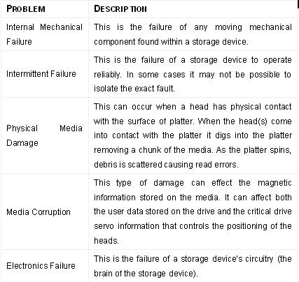
Types of common failures include:

As we know, hard drives are a combination of sophisticated electronic and mechanical systems that incorporate a number of specialized motors and electro-mechanical components to read and write data.

Hard drive technology has substantially advanced in the past 10 years. In fact, hard drives are designed to manage themselves in addition to reading and writing data. Hard drives today use a number of algorithms to verify data on the drive and also maintains a ‘Defect Management’ list internally that constantly monitors their own health and performance. If a sector is beginning to fail, the hard drive’s electronics will remove that sector from use. In addition to this, S.M.A.R.T. (Self-Monitoring, Analysis and Reporting Technology) circuitry has been incorporated on many hard drives and is used to monitor all of the internal systems.

Despite these safeguards, hard drives can fail. There can be a number of reasons for hard drive failure, for instance physical damage can result when the hard drive or case is jarred while operating or even when powered off. Power spikes or fluctuations can damage the electronics or corrupt the data on the drive. Internal mechanical parts can seize up due to high temperatures if the drive does not have enough airflow to keep the unit cool.

Read More

Platter Scratch Repairing

Hard Disk Drive Crash
Take the case of computer systems. We become so used to working on the computer on a regular basis that we are rarely ready to face the consequences if things go wrong. This is truer of a computer hard disk drive crash than of anything else. Hard drive malfunction can be divided into two types: one is the so called Firmware Level malfunction that can be repaired using relating software or factory commands; the other one left is the Physical Level malfunction caused by physical hard drive components damage. As to the latter Physical Level crash, the typical case in data recovery practices is that the head crash and serious platter scratches caused by direct contact between the head and the platter surface; such drives manifest themselves as undetected, staying BUSY, besides an ominous scratching sound may start to emanate from the disk. This is a serious problem. It is indicative of nothing less than a crash of the hard disk drive.

Functioning of a Hard Disk Drive
In order to understand the problem of a hard disk drive crash, it is important to first understand the mechanism of a hard drive. Only after knowing how the disk drive functions can one understand the nature of the problem.

Components
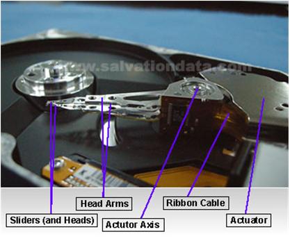
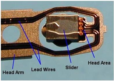
Read-Write Head: The read-write heads of the hard disk drives are those mechanisms that, as the name suggests read or write the data from the magnetic fields of the platters.

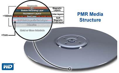
Hard Disk Platter: A hard disk platter is a circular disk within the hard disk drive. It is circular in shape and the magnetic media of the disk drive is stored on it. Generally multiple platters are mounted on a single spindle of the hard disk drive.

Lubricant Layer: This is the topmost layer of the platters and is made of a substance similar to Teflon. Carbon: There is a layer of sputtered carbon just below the lubricant layer. Magnetic Layer: This is below the layer of carbon.

Functioning
The magnetic layer of the hard disk drive stores all the data. The two layers of carbon and the lubricant like material saves this magnetic layer from coming into accidental contact with the read-write head of the disk, we can say they exist as the protection layer of the magnetic layer (of course, another important function of them is to maintain the stability of the flying read-write head)

Read More

File Systems

Different operating systems use different file systems. Some are designed specifically to work with more than one, for compatibility reasons; others work only with their own file system. This section takes brief look at the most common operating systems in use on the PC and the file systems that they use. This enables you to know what parts of the rest of the discussion on file systems is most relevant to your situation.

The most common name of the file system, “FAT”, is problematic, even though it is still often used. The first FAT file system used 12-bit file allocation tables; this was later expanded to 16 bits, and became the most common file system implementation for hard disks from the late 1980s to the late 1990s. To distinguish these versions of FAT from the 32-bit successor called FAT32, the older FAT variants are now sometimes called FAT12 or FAT16. However, you will still hear just “FAT” used a lot; if so, you need to find out what specifically is being referred to, if it matters in that particular context. For more elaboration on the differences between FAT12, FAT16 and FAT32.

Throughout my discussion of file systems, I have referred to the FAT family of file systems. This includes several different FAT-related file systems, as described here. The file allocation table or FAT stores information about the clusters on the disk in a table. There are three different varieties of this file allocation table, which vary based on the maximize size of the table. The system utility that you use to partition the disk will normally choose the correct type of FAT for the volume you are using, but sometimes you will be given a choice of which you want to use.

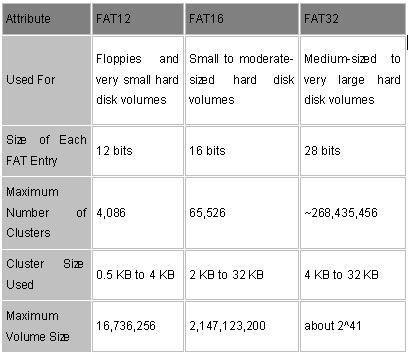
Since each cluster has one entry in the FAT, and these entries are used to hold the cluster number of the next cluster used by the file, the size of the FAT is the limiting factor on how many clusters any disk volume can contain. The following are the three different FAT versions now in use:

  • FAT12: The oldest type of FAT uses a 12-bit binary number to hold the cluster number. A volume formatted using FAT12 can hold a maximum of 4,086 clusters, which is 2^12 minus a few values (to allow for reserved values to be used in the FAT). FAT12 is therefore most suitable for very small volumes, and is used on floppy disks and hard disk partitions smaller than about 16 MB (the latter being rare today.)
  • FAT16: The FAT used for most older systems, and for small partitions on modern systems, uses a 16-bit binary number to hold cluster numbers. When you see someone refer to a “FAT” volume generically, they are usually referring to FAT16, because it is the de facto standard for hard disks, even with FAT32 now more popular than FAT16. A volume using FAT16 can hold a maximum of 65,526 clusters, which is 2^16 less a few values (again for reserved values in the FAT). FAT16 is used for hard disk volumes ranging in size from 16 MB to 2,048 MB. VFAT is a variant of FAT16.
  • FAT32: The newest FAT type, FAT32 is supported by newer versions of Windows, including Windows 95’s OEM SR2 release, as well as Windows 98, Windows ME and Windows 2000. FAT32 uses a 28-bit binary cluster number–not 32, because 4 of the 32 bits are “reserved”. 28 bits is still enough to permit ridiculously huge volumes–FAT32 can theoretically handle volumes with over 268 million clusters, and will support (theoretically) drives up to 2 TB in size. However to do this the size of the FAT grows very large; see here for details on FAT32’s limitations.
  • Here’s a summary table showing how the three types of FAT compare:


    Virtual FAT (VFAT)
    Microsoft incorporated several enhancements into the disk management capabilities of Windows 95. Access to the file system can be done using high-speed, protected-mode, 32-bit drivers, or for compatibility, the older DOS 16-bit routines. Support was added for long file names and also for better control over such matters as disk locking, so utilities could access the disk in “exclusive mode” without fear of other programs using it in the meantime.

    Despite the new name and new capabilities, VFAT as a file system is basically the same as FAT is. Most of the new capabilities relate to how the file system is used, and not the actual structures on the disk. VFAT handles standard FAT16 partitions, and under Windows 95 OSR2 or later, FAT32 partitions as well. The only significant change in terms of actual structures is the addition of long file names. Even here, VFAT supports these using what is basically a hack, as opposed to anything really revolutionary.

    With the exception of the long file names, Windows 95, using VFAT, shares the same logical disk structures as DOS or Windows 3.x using FAT.

    NTFS
    The NTFS file system used by Windows NT is completely different from, and incompatible with, the FAT file system that is used by DOS and the other Windows varieties. NTFS can only be used by Windows NT–other operating systems do not have the ability to use a disk formatted with NTFS.
    NTFS is in virtually every way, far superior to FAT. It is a robust, full-featured system that includes file-by-file compression, full permissions control and attribute settings, transaction-based operation, and many more features. It also does not have the problems with cluster sizes and hard disk size limitations that FAT does, and has other performance-enhancing features such as RAID support.

    The only way that NTFS is not superior to FAT is in compatibility with older software. NTFS is not nearly as widely-used as FAT, for this reason. For now I am not including a full examination of NTFS on the site, but I may add this at a later time if it seems warranted.

    Read More

    Hard Drive Firmwares

    Definition of firmware:
    Since modern hard disks have internal microprocessors, they also have internal “software” that runs them. These routines are what run the control logic and make the drive work. Of course this isn’t really software in the conventional sense, because these instructions are embedded into read-only memory. This code is analogous to the system BIOS: low-level, hardware-based control routines, embedded in ROM. It is usually called firmware, with the word “firm” intending to connote something in between “hard” and “soft”. The functions that run the logic board’s circuitry could be implemented strictly with hardware devices, as was done with early drives. However, this would be expensive and inflexible for today’s sophisticated controllers, since it would make it difficult to update or adapt the logic to match changes in hard disks or the devices they interface with.

    Much the way the system BIOS benefits from being in a changeable ROM chip that can be modified relatively easily, the hard disk’s firmware does as well. In fact, in many drives the firmware can be updated under software control, very much the same way that a flash BIOS works. Unlike the system BIOS, this is only very rarely done, when a particular sort of problem exists with the firmware logic that can be fixed without requiring a physical hardware change. You can check the drive manufacturer’s web site for more details.

    In short, without the firmware code, no communication will be possible between the PC system and the hard disk.

    Where the firmware stores?
    Modern disks normally have their firmware codes located on data platters and also the PCB board. If the firmware area is corrupted, the drive will appear to have failed even all the electrical and mechanical components are still fully functional.

    You may know the importance of firmware on the HDD function. And know the firmware is like the micro codes between the elements of HDD. And what will it happen if there are some firmware corruptions?

    Let’s see the symptoms of firmware corruption before the solutions given:

    1. Drive powers up, but is not recognized /defected by the computer
    2. Drive powers up, but is recognized wrongly, sometimes with nonsensical characters, manufacture alias (Such as N40p for Maxtor 6Y and etc ;);
    3. Drive freezes during booting up;
    4. Drive detect in wrong Capacity, such as 80 GB detected as 1Mb;
    5. S.M.A.R.T error;
    6. Drive is locked by human error; such as Hitachi hard drive by a drop; it is a self protection method of HDD design;
    7. Drive clicking ;( it can be caused by firmware too, the heads try to read the SA on platters and can not positing 😉

    The firmware is very confidential to common users and the HDD manufacturers will never publish to the public.

    Read More

    Data Interface Connector or Card

    Modern hard disk drives use one of two interfaces: IDE (ATA) – Integrated Drive Electronics (also called ST506 drives) and its variants (EIDE – Enhanced Integrated Drive Electronics, or the SCSI (Small Computer System Interface). You can tell immediately by looking at the back of the hard disk which interface is being used.

    1. IDE hard disks use a 40-pin connector, and SCSI hard disks normally use either a 50-pin or a 68-pin or 80-Pin connector.

    2. Note: Older MFM (MODIFIED FREQUENCY MODULATION), RLL (RUN LENGTH KIMITED) and ESDI (ENHANCED SYSTEM DEVICE INTERFACE) hard disks used two data connectors, one 34 pins and the other 20 pins.

    3. The cable usually has a red stripe to indicate wire #1 and the hard disk uses markers to indicate the matching pin #1.

    Led Connector: Originally, hard disks shipped with a faceplate (or bezel) on the front. The hard disk was mounted into an external hard drive bay (in place of a floppy disk drive) and an LED was visible on the front of the drive to indicate when the disk was in use. It was quickly realized that having the disks mounted internally to the case made more sense, but the LED was still desirable. So an LED was mounted to the case and a wire run to a two-pin connector on the hard disk itself. On newer systems that run with integrated IDE controllers on the motherboard, the LED is connected to a special connector on the motherboard itself.

    Drive Bay: The entire hard disk is mounted into a physical enclosure designed to protect it and also keep its internal environment sealed from the outside air. This is necessary because of the requirement of keeping the internal environment free of dust and other contamination that could get between the read/write heads and the platters over which they float, and possibly lead to head crashes.

    DRIVE BAYS are where internal hard drives are mounted inside the PC. They come in internal and external versions, based on whether they allow access from the exterior of the case, and also in two standard sizes: 5.25″ and 3.5″.

    Now, we have rough understanding of the HDD components now and how these parts work in architecture. But you may find the importance of the microprogram inside the HDD. No matter how precise the HDD design, they are a stack of meaningless mechanical parts.

    Read More

    PCBA, control circuitry (Printed Circuit Board Assembly)

    All modern hard disks are made with an intelligent circuit board integrated into the hard disk unit. Early hard disks were virtually all of the control logic for controlling the hard disk itself was placed into the controller plugged into the PC; there were little smarts on the drive itself, which had to be told specifically how to perform every action.

    As newer drives were introduced with more features and faster speed, this approach became quite impractical, and once electronics miniaturization progressed far enough, it made sense to move most of the control functions to the drive itself.

    The most common interface for PC hard disks is called IDE, which in fact stands for Integrated Drive Electronics. This name is something of a misnomer today. When it was introduced, IDE was distinguished from the other interfaces of the day by having the integrated electronics on the drive, instead of on the controller card plugged into the system bus like older interfaces. However, the term really refers to where the control logic is and not the interface itself, and since all hard disks today use integrated electronics the name doesn’t mean anything any more, despite the fact that everyone continues to use it. The other popular PC hard disk interface today, SCSI, also uses drives that have integrated controllers. The more correct name for the IDE interface is AT Attachment or ATA.
     
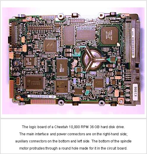
    The logic board of a Cheetah 10,000 RPM 36 GB hard disk drive.The main interface and power connectors are on the right-hand side;auxiliary connectors on the bottom and left side. The bottom of the spindlemotor protrudes through a round hole made for it in the circuit board. 

    What’s the relationship between PCBA and Control Circuitry? Let me give an example. The electric current is like Blood and the Control Circuitry is like the blood vessel distributing on the HDD, and the PCBA is like the brain to process and give orders to particular parts.

    The drive’s internal logic board contains a microprocessor (inside main chip) and internal memory (RAM chip), and other structures and circuits that control what happens inside the drive.

    In many ways, this is like a small embedded PC within the hard disk itself. The control circuitry of the drive performs the following functions (among others):

    1. Controlling the spindle motor, including making sure the spindle runs at the correct speed.
    2. Controlling the actuator’s movement to various tracks.
    3. Managing all read/write operations.
    4. Implementing power management features.
    5. Handling geometry translation.
    6. Managing the internal cache and optimization features such as pre-fetch.
    7. Coordinating and integrating the other functions, such as the flow of information over the hard disk interface, optimizing multiple requests, converting data to and from the form the read/write heads require it, etc.
    8. Implementing all advanced performance and reliability features.

    You may think that the Control Circuitry is not so important. The reason is that the quality or optimization level of the control circuitry doesn’t manifest itself as a single, simple specification. You can’t easily compare the circuitry of five different drive families. Most hard disk manufacturers provide very little information about the “guts” of the logic board, and even if they did, most people wouldn’t know what to do with the information.

    However, the control circuitry of the drive is underrated and misunderstood, even by those interested in hard disk performance issues.

    In fact, differences in control circuitry account for part of the differences in some specifications. This is probably most true of seek performance, Beyond this, you can’t really tell much about what’s inside the circuitry. However, if you use two different drives that have very similar specifications and run on the same interface on the same PC, but one just “feels faster” than the other, differences in their internal circuitry may be part of the answer.

    Read More