DATARECOVERYUNION.COM

Hard Disk Drive Controller

Since digital information is a stream of ones and zeros, hard disks store information in the form of magnetic pulses. In order for the PC’s data to be stored on the hard disk, therefore, it must be converted to magnetic information. When it is read from the disk, it must be converted back to digital information. This work is done by the integrated controller built into the hard drive, in combination with sense and amplification circuits that are used to interpret the weak signals read from the platters themselves.

In short, the disk controller consists of a ROM that embedded some disk commands to translate and implement some write and read orders from a PC, it is like a disk controller chip, and a little glue to make it all work.

I used to imagine that a Hard disk controller is a talented translator who lives in a chip of PCB, translating between the magnet signal of ones of HDD and zeros and commands from PC.

Modern disk controllers are integrated into the disk drive. For example, disks called “SCSI disks” have built-in SCSI controllers. In the past, before most SCSI controller functionality was implemented in a single chip, separate SCSI controllers interfaced disks to the SCSI bus.

The most common types of interfaces provided nowadays by a disk controller are ATA (IDE) and Serial ATA for home use. High-end disks use SCSI, Fibre Channel or Serial Attached SCSI.

Read More

Hard Drive Spindle Motor

The spindle motor, also sometimes called the spindle shaft, is responsible for turning the hard disk platters, allowing the hard drive to operate. The spindle motor is sort of a “work horse” of the hard disk, like a heart of human, it give the motivity of power to the HDD. It’s not flashy, but it must provide stable, reliable and consistent turning power for thousands of hours of often continuous use to allow the hard disk to function properly. In fact, many drive failures are actually failures with the spindle motor, not the data storage systems, such as that the motor bearing seizure, Motor not spin.

The spindle motor has several important commitments placed upon it. First, the motor must be of high quality, so it can run for thousands of hours, and tolerate thousands of start and stop cycles, without failing. Second, it must be run smoothly and with a minimum of vibration, due to the strict tolerances of the platters and heads inside the drive. Third, it must not generate excessive amounts of heat or noise. Fourth, it should not draw too much power. And finally, it must have its speed managed so that it turns at the proper speed, neither faster nor slower.

I’ve found that the weather is one of the factors which effect the lifetime of HDD. From some customers from Africa, there are more haunted by the Motor stuck problems than any other places. For some HDD used on server have more demands on the tolerance and quality, they are supposed to be work at 7X24 a week.

To meet these demands, all PC hard disks use servo-controlled DC spindle motors. A servo system is a closed-loop feedback system; this is the exact same technology as is used in modern voice coil actuators. Let’s see how servo systems work in detail. In the case of the spindle motor, the feedback for the closed-loop system comes in the form of a speed sensor. This provides the feedback information to the motor that allows it to spin at exactly the right speed.

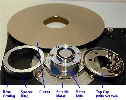
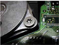
All hard disk spindle motors are configured for direct connection; there are no belts or gears that are used to connect them to the hard disk platter spindle. The spindle onto which the platters are mounted is attached directly to the shaft of the motor. The platters are machined with a hole at the exact size of the spindle, and are placed onto the spindle with separator rings (spacers) between them to maintain the correct distance and provide room for the head arms. The entire assembly is secured with a head cap and usually, lots of small Torx screws.

! By design, TORX head screws resist cam-out better than Phillips head or slot head screws. Where Phillips heads were designed to cause the driver to cam out, to prevent over-tightening, TORX heads were designed to prevent it. The reason for this was the development of better torque-limiting automatic screwdrivers for use in factories. Rather than relying on the tool slipping out of the screw head when a torque level is reached, and thereby risking damage to the driver tip, screw head and workpiece, the drivers were designed to achieve a desired torque consistently. Camcar LLC claims this can increase tool bit life by ten times or more.

One important quality issue that has become a focus of attention with newer hard disks is the amount of noise, heat and vibration they generate. The reason for this becoming more of an issue is the increase in spindle speed in most drives. On older hard disks that typically spun at 3600 RPM, this was much less of a problem. Some newer drives, especially 7200 and 10,000 RPM models can make a lot of noise when they are running. If possible, it’s a good idea to check out a hard disk in operation before you buy it, to assess its noise level and see if it bothers you; this varies greatly from individual to individual. Heat created by the spindle motor can eventually cause damage to the hard disk, which is why newer drives need more attention paid to their cooling. Newer high-speed drives almost always run cooler and quieter than the first generation of drives at any new spindle speed. It can be painful to be a pioneer;

Read More

Head-Actuator Assembly

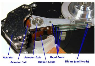
We often call the Head-Actuator Assembly as head stacks or only heads for short. In fact, we make a mistake in some way. Let’s take a look at a head-actuator Assemble on the flowing photo:

Mostly, each platter is accessed for read /write operations using two read/write heads, one mounted on the top of the platter and another on the bottom. These heads are mounted onto arms that allow them to be moved from the outer tracks of the hard drive to the inner tracks and back again. The arms are controlled using a device called an actuator that positions the arms to the appropriate track on the disk. The read/write heads don’t touch the platter when the platter is spinning at full speed; instead, they float on an extremely thin cushion of air (10 millionths of an inch, Winchester disk drive). That’s why power surge may cause Head crash and platter scratch due to the fast rotating rolling of platters.

Notice: In 1973, IBM introduced the IBM 3340 “Winchester” disk drive, the first significant commercial use of low mass and low load heads with lubricated media. All modern disk drives now use this technology and/or derivatives thereof. Project head designer/lead designer Kenneth Haughton named it after the Winchester 30-30 rifle after the developers called it the “30-30” because of it was planned to have two 30 MB spindles; however, the actual product shipped with two spindles for data modules of either 35 MB or 70 MB.

How they work?
The hard disk platters are accessed for read and write operations using the read/write heads mounted on the top and bottom surfaces of each platter. Obviously, the read/write heads don’t just float in space; they must be held in an exact position relative to the surfaces they are reading, and furthermore, they must be moved from track to track to allow access to the entire surface of the disk. The heads are mounted onto a structure that facilitates this process. Often called the head assembly or actuator assembly (or even the head-actuator assembly), it is comprised of several different parts.

The heads themselves are mounted on head sliders. The sliders are suspended over the surface of the disk at the ends of the head arms. The head arms are all mechanically fused into a single structure that is moved around the surface of the disk by the actuator. (Sort of like “the wrist connected to the hand”, why I say it is a hand because it is very skillful and ingenious and the upper site is Arm: D).They play an important role in the function and performance of the drive. In particular, advances in slider, arm and actuator design are critical to improving the seek time of a hard disk.

Read More

WD HDDs Noise related to PCB

The Causes & Solutions of Two Main types of Noise which is occurred in WD HDDs (Especially Related To L-shape PCBs).Continuous Noise & Clicking Noise
1- The Continuous Noise

Sometimes there is a continuous noise come from WD HDDs mainly with L-shape PCBs
with motor ICs (Smooth 1.3) , (L6278 1.7) & (L6278 1.2).
the noise is like : Trrrrrrrrrrrrrr or Trrrr….Trrrr…Trrrrr

so all we have to do for fixing this problem is:

1- clean the connection points which connect the head stack pins with the PCB using a pencil Rubber …carefully.

2- clean the motor IC pins thoroughly using a solvent & Toothbrush then wipe it with a piece of smooth handkerchief to remove the dust & dirt from it.

-Note- the two steps mentioned above solve the problem in few cases.

3- If the two steps mentioned above didn’t fix the problem , you have to replace the motor IC cause it’s damaged.

2-The Clicking Noise
when u power on the hard drive u will hear a noise like (click,click….click,click…click,click)
this noise may be related to the head stack or PCB, the first thing you have to do is to check the PCB By The following steps:

1- first u have to clean the Whole PCB With a Solvent & Toothbrush then wipe it with a piece of smooth handkerchief to remove the dust & dirt from it.
Caution: Cleaning of the PCB must be done carefully to avoid removal of any small electronic components.

2- Check the Resistor (R120) , [ the right value of this Resistor is (0.12 Ohm) ] ,you may adjust your multimeter to Resistor Measuring Mode to Determine its Value ,if it’s Damaged u have to replace it. but before that, u have to check Transistor Q3 , it’s a 6 pins transistor , for measuring this transistor u may adjust your multimeter to Diode Mode,[ the right Value will be: (first two pins = 0.000 , second two pins =0.000 , Third two pins = nearly over 600)]
if Q3 is Damaged it will burn ur R120 after u replace it , so be sure that Q3 is ok before replacing R120 & u may also Check Transistor Q6 by the previous method to be completely sure it’s safe to replace R120.
Note: ( to be sure of The right values of these electronic components u may compare the values u have measured with the values of a working PCB’s Components)

3- Check The Coils (such as L2 & L7) – adjust your multimeter to diode mode then the right value must be ( 0.000 ) for any coil as u all know.

4- Inspect the whole PCB for any removed component ( such as small capacitors or Resistors ) … the removal of these small components may occurred while forced cleaning of the PCB …. so be careful while cleaning it.

5- In rare cases the firmware microchip may be damaged.

——————————————————————————————

-Note- in case of Motor ICs (L6278 1.7) & (L6278 1.2) first try to desolder them then resolder them again before u decide to replace them with a new ones … this sometimes work , but if it didn’t work … replace them directly.
– in case of Motor IC (Smooth 1.3) you must replace it directly.

The image below shows you where to clean.

Read More

Hard drive sectors

Each track is further broken down into sectors. A sector is normally the smallest individually-addressable unit of information stored on a hard disk. Each sector of data on the hard disk contains 512 bytes, or 4,096 bits, of user data (1 byte=8 bits it is octal). In modern drives the larger outer tracks hold more sectors than the smaller inner ones. All information stored on a hard disk is recorded in tracks. The tracks are marked by number, starting from zero, starting at the outside of the platter and increasing in number as you go in.

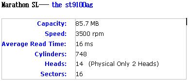
The first PC hard disks typically held 16 sectors per track. Details as below from Seagate

Capacity:Speed:Average Read Time: Cylinders:Heads:Sectors: 85.7 MB3500 rpm16 ms74814  (Physical Only 2 Heads)16

Resource:  Examples: 16 (e.g. the st9100ag), 17 (e.g. the st325ax), 24 (e.g. the st9190ag), 27 (e.g. the st280a), 28 (e.g. the Maxtor 8051A), 29 (e.g. the st1162a), 32 (e.g. the st9051a), 34 (e.g. the st3195a), 35 (e.g. the st3283a), 36 (e.g. the st1239a), 38 (e.g. the st3211a), 47 (e.g. the st9150ag), 50 (e.g. the st3291a), 51 (e.g. the st9385ag), 52 (e.g. the st9240ag), 53 (e.g. the st3271a), 55 (e.g. the st2274a), 56 (e.g. the st2383a), 59 (e.g. the st9550ag), 60 (e.g. the st9300ag), 61 (e.g. the st1401a), 62 (e.g. the st3385a), 63 (e.g. the st3270a).

(Please go to Seagate website to get the details of above HDD.)

A sector includes only 512 Bytes?
In addition to these bits (512 Bytes of user data), an additional number of bits are added to each sector for the implementation of error correcting code or ECC (sometimes also called error correction code or error correcting circuits). These bits do not contain user data; rather, they contain information about the data that can be used to correct any problems encountered trying to access the real data bits.

Block Mode: More than one sector can be transferred on each interrupt notification. Newer drives allow you to transfer as many as 16 or 32 sectors at a time. These sectors are known as Clusters. On some systems you will find an option in the system BIOS called block mode. You may set it on BIOS.

Block mode is a performance enhancement that allows the grouping of multiple read or write commands over the IDE/ATA interface so that they can be handled on a single interrupt.

Example of a BIOS option for the IDE Block Mode feature (boxed in red)

Read More

Hard Drive Platters

Platters in physical
The physical material of Platters: Aluminum alloy comprises the physical material of the platter. It is rigid, easy to work with, lightweight, stable, inexpensive and readily available. The speed that the platters spin is increasing to store data much quicker and in intensive tracks, it is creating more demands on the platter material itself. That’s why the first glass Platters of IBM HDD failed to dominate the market;

Media Layer: The physical material (Aluminum alloy) of which the platters are made forms the base upon which the actual recording media is deposited. The media layer is a very thin coating of magnetic material which is where the actual data is stored, typically only a few microinches in thickness. The media layer is usually comprised of a special alloy. That’s why the data will lose or inaccessible by ages of using. It is because the thin media layer become dull or damaged and can’t react the signals from the HDD or commands from a PC;

Does it make any sense to wash Platters with distilled water or alcohol?
You must laugh at my silly question. But it happened, someone told me before that He did wash the platters with pipe water because there are many fingerprints on them, and, huh, according to his words, he had fixed it and that drive got working.

Can we put the hard drive near with some magnetic materials?
People put the hard drive in some antistatic storage and they avoid to put their credit cards and other magnetic cards together.

Protective Layer: The surface of each platter is normally covered with an extra-thin, protective, lubricating layer, on top of the magnetic media layer itself. This material is used to protect the disk from damage caused by accidental contact from the heads or other foreign matter that might get into the drive. That’s why you can use your HDD to store data for years, not for a couple of months;

Platters in Logically
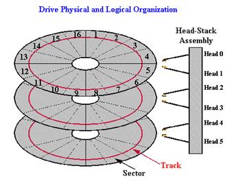
Platters Divisions: The platter is divided into Tracks and Sectors and is read by Zone Recording or Clusters.

Tracks:
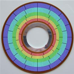
Platters are organized into specific structures to enable the organized storage and retrieval of data. Each platter is broken into several thousand tracks, which are   tightly-packed concentric circles. (These are similar in structure to the annual rings of a tree.,see the circle in red of the Picture).

But, you will find that the ones on the outside of the platter are much larger than the ones on the inside–typically double the circumference or more. Since there is a constraint on how tight the inner circles can be packed with bits, they were packed as tight as was practically possible given the state of technology, and then the outer circles were set to use the same number of sectors by reducing their bit density. This means that the outer tracks were greatly underutilized, because in theory they could hold many more sectors given the same linear bit density limitations.

To eliminate this wasted space, modern hard disks employ a technique called zoned bit recording (ZBR), also sometimes called multiple zone recording or even just zone recording. With this technique, tracks are grouped into zones based on their distance from the center of the disk, and each zone is assigned a number of sectors per track. As you move from the innermost part of the disk to the outer edge, you move through different zones, each containing more sectors per track than the one before. This allows for more efficient use of the larger tracks on the outside of the disk.

Read More

NTFS Master File Table (MFT)

Each file on an NTFS volume is represented by a record in a special file called the master file table (MFT). NTFS reserves the first 16 records of the table for special information. The first record of this table describes the master file table itself, followed by a MFT mirror record. If the first MFT record is corrupted, NTFS reads the second record to find the MFT mirror file, whose first record is identical to the first record of the MFT. The locations of the data segments for both the MFT and MFT mirror file are recorded in the boot sector. A duplicate of the boot sector is located at the logical center of the disk.

The third record of the MFT is the log file, used for file recovery. The seventeenth and following records of the master file table are for each file and directory (also viewed as a file by NTFS) on the volume.

Figure provides a simplified illustration of the MFT structure:

Figure 5-2 MFT Structure


The master file table allocates a certain amount of space for each file record. The attributes of a file are written to the allocated space in the MFT. Small files and directories (typically 1500 bytes or smaller), such as the file illustrated in next figure, can entirely be contained within the master file table record.

Figure 5-2 MFT Record for a Small File or Directory:


This design makes file access very fast. Consider, for example, the FAT file system, which uses a file allocation table to list the names and addresses of each file. FAT directory entries contain an index into the file allocation table. When you want to view a file, FAT first reads the file allocation table and assures that it exists. Then FAT retrieves the file by searching the chain of allocation units assigned to the file. With NTFS, as soon as you look up the file, it’s there for you to use.

Directory records are housed within the master file table just like file records. Instead of data, directories contain index information. Small directory records reside entirely within the MFT structure. Large directories are organized into B-trees, having records with pointers to external clusters containing directory entries that could not be contained within the MFT structure.

Read More

The basic knowledge about Hard Disk Drive

Firmware files that you can find on a site like this, contain a lot of files. First, there is the ‘loader’ file (*.LDR). This file is the ‘temporary’ firmware code, that’s being uploaded to the RAM (so, it’s not being written to disk). Then, there are a lot of ‘*.RPM’ files. These files represent the different modules, which can be written to the SA. The filenames consist of 8 numbers. The first 4 numbers specify the (hex) UBA and the second 4 numbers represent the hexadecimal module size in sectors (each sector normally contains 512 bytes, so for example, if a filename ends in 0002, then that module is 1024 bytes long). So, in short, after uploading the loader to RAM, the user can start replacing damaged modules by overwriting them with correct ones.BTW, please note that the term ‘firmware’ for the packages on this site is symantically not very well chosen, since these packages contain all needed modules to repair a HDD and not just the firmware (=code) module.
Anyway, if you’re looking for a specific firmware module, you can do 3 things:
1) rip the firmware modules from the SA of an identical HDD
2) get these modules from a friend (or for example, from the files section on this site)
3) use a firmware updater program from the vendor.

About this last option: firmware updates from vendors are pretty rare, since firmware code almost never needs to be replaced. However, Maxtor for example, had some problems with the firmware code on some Diamondmax HDD models. So, they issued a firmware update. This update consists of 2 files:

1) the executable file that issues the ATA ‘download microcode’ command to upload the firmware files to the HDD
2) The firmware code, consisting of the ‘main’ firmware code and ‘overlay’ code modules.

Firmware ‘overlay’ code are specific code functions. Why not just put all firmware code into one section ? Well, since the RAM in the drive is a limited resource, they’ve put some code into ‘overlay files’, so that this specific code can be swapped into RAM when that specific function is needed. When the fuction is not needed, it can be swapped out of ram and some other function can be swapped into it again.

The firmware update files from maxtor (I think the same goes for the other vendors) are not scrambled/encrypted/packed in anyway. In fact, you can find the exact same code in these files also in the ‘*.RPM’ files that PC3K produces for example.

Maxtor distributes their firmware file in a so called “.DMC” file. This DMC file is a package of 4 files, a ‘.Bxx’ file, a ‘.cxx’ file, a ‘.bbr’ file and a ‘.cbr’ file. Like I mentioned, this DMC container is not packed or scrambled in anyway. You can just cut the files out of it. The first 0x150 bytes of this file is the header. This header contains the four filenames, the offsets at which bytes in the package these files can be found, the length of the files and a checksum (not 100% sure about the checksum though). The ‘.bxx’ file is the biggest file and contains the overlay modules. You can find all code overlay modules by looking for ‘MO’ in the file. Right after this 2 byte string, you’ll find the hexadecimal overlay module ID. The ‘.bbr’ file contains the main firmware code. The last 2 files are very small, not sure what they contain, probably some checksums for the firmware and overlay modules.

Like said, the firmware code and overlay modules can also be found in the ‘*.RPM’ files of course, since this represents the firmware code on disk. So, you can look through these RPM files and scan for the ‘MO’ string to find any specific overlay module.

So, in short, if a vendor has released a firmware uploader tool (most vendors have), BUT haven’t released a firmware file for your specific drive type, you could create your firmware, if you have the dumped modules (for example, obtained from this site). You could rip the main code and overlay modules and paste them into an existing DMC package. However, since I don’t know the checksum calculation and the meaning of these .cxx and .cbr files (probably checksums), you’d have to do more research, but in theory, it would be possible to create your own firmware files and flash them with such standard Vendor program to disk, so you wouldn’t need to buy an expensive tool like PC3000 (at least not if your sole goal was to upload a new firmware).

Modern hard disks feature an area that contains information that the CPU on the HDD logic board uses to operate the drive. That area is called the “system area” SA. This area contains for example the drive ‘microcode’ (a.k.a. firmware), HDD Configuration Tables, Defect sector tables, SMART information, Security info (drive passwords etc), Disk ID info (serial nr etc) and more. These categories of information are called ‘modules’. So the SA contains a module for the firmware code, a module for the SMART info etc.The SA is stored on ‘negative cylinders’ of the HDD and therefore is not accessible by normal read commands. However, the area can be accessed with other ATA commands. An example of a (more or less) ‘standard’ ATA command that can access info on the SA is the ‘download microcode’ ATA command, which can be used to update information in the firmware code module. However, most of the commands that can be used to access the SA are vendor specific. Since vendors (obviously) don’t want users to mess around with the SA, these commands are generally not made public. However, these commands can be deduced by, for example, reverse engineering the firmware code itself.
This reverse engineering has been done and led to development of tools that can issue these (vendor specific) ATA commands and can read/write almost all sectors in the SA. One example of such tool is PC3000. A tool like this contains tables per HDD model, containing these vendor specific ATA commands and also tables with sector numbers on which the different modules are stored, also per HDD model. SA Sector numbers are counted in “UBA’s”. For example, one specific HDD might use UBA 4 to store the ‘DISK ID’ module, where another HDD model might use another sector for this module.
So in short, to create a tool that can read/write data in the SA, you need to:

A) know (and understand) the (vendor-) specific ATA commands that can be used to access this area and
B) know on which UBA sector the specific modules are stored.

If a drive has damaged data in the SA, for example in the firmware code module, it might become unusable. To repair these disks, the HDD can be switched to a so called ‘safe mode’, by setting specific jumpers on the drive. If the drive is operating in safe mode, it bypasses its own firmware. Instead, it wants the user to upload firmware to its ram. If the user uploads a correct ‘temporary’ firmware to RAM, it starts executing that firmware. If this uploaded RAM code (the ‘loader’) starts operating, the user can then start to issue ATA commands to the drive to modify the damaged modules.

Of course, you could also create your own flasher program, instead of using the one supplied by the vendor. However, since vendors use specific versions of the ‘download microcode’ ATA command, you’d have to do research into this.

Furthermore, you could create a program that does EVERYTHING that a tool like PC3000 does. However, like pointed out, you’ll need very detailed information on the vendor specific ATA commands and the structure of the SA for that specific drive type and since this info is not made public by anyone, this means a LOT of work. “But hey, the PC3000 tool features a special hardware PCI card!” Yes, but as you’ll understand by now, you can think of that card as nothing more than a copy protection. They could have perfectly created the tool without it, but I guess they would have sold quite some copies less. So you really can’t blame them for it, in fact, I think it’s quite a smart move to stop piracy.

So, in short, if you want to mess around with the SA, you have 2 options: invest a lot of time and energy into learning or simply empty your pockets and buy a tool like PC3000.

Read More

What a hard drive looks like?

 To many people, a hard disk is a “black box” of sorts—-it is thought of as just a small device that “somehow” stores data. There is nothing wrong with this approach of course as long as all you care about is that it stores data. It is hard to really to understand the factors that affect performance, reliability and interfacing without knowing how the drive works internally.

If you use your hard disk as more than just a place to “keep stuff”, then you want to know more about your hard disk. For those people who earn their butter and bread by retrieving data from a defect hard drive, it is necessary to know how the hard drives works know more the ticks of store data.

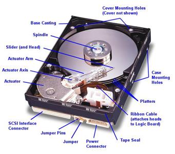
Fortunately, most hard disks are basically the same on the inside. While the technology evolves, many of the basics are unchanged from the first PC hard disks in the early 1980s. Lets have a look at the following pictures of a modern SCSI hard disk, with major components annotated from Western Digital Corporation):

(Original image � Western Digital Corporation)

We look at the various key components, discuss how the hard disk is put together, and explore the various important technologies and how they work together to let you read and write data to the hard disk. My goal is to help you really understand the design decisions and tradeoffs made by hard disk engineers, and the ways that new technologies are being employed to increase capacity and improve performance.

When the first HDD looked like? What was the capacity of it?
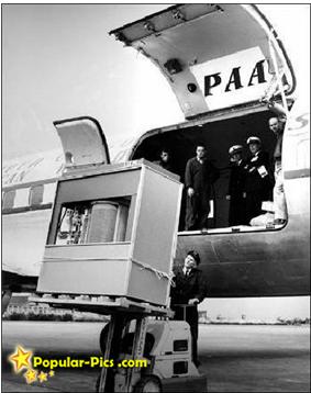
5MB Hard Disk in 1956
It’s a hard disk in 1956…. the Volume and Size of 5MB memory storage in 1956. In September 1956 IBM launched the 305 RAMAC, the first computer with a hard disk drive (HDD). The HDD weighed over a ton and stored 5MB of data. Let us start appreciating your 4 GB jump drive!

5MB Hard Disk in 1956 – Its a hard disk in 1956…. The Volume and Size of 5MB memory storage in 1956. In September 1956 IBM launched the 305 RAMAC, the first computer with a hard disk drive (HDD). The HDD weighed over a ton and stored 5MB of data.

Read More

Information on data recovery

The three most common problems seen today are: 1. The drive makes a repetitive clicking sound when power is applied (this may not always be audible to you). 2. The drive is completely dead, not spinning at all. 3. The computer bios sees the drive, but there is no boot and a boot from a floppy will not gain access or you get an error message that says ‘Invalid media type reading drive X’. Of course there are other issues such as flooding (never turn a wet drive on!), fire and other natural and unnatural disasters all of which require a top-notch data recovery company to work with.

If your drive is making a clicking sound, 9 times out of ten this means that the heads are bad and cannot read the information needed to get the drive to a ‘ready’ state. This can be due to two factors: physical head crash whereas the heads scrape some of the media off the surface of the platters thus destroying the heads in the process or the heads just go bad. The result is the same, the drive clicks. In this type of situation, you can expect an expensive data recovery because of what is needed to extract the data. The drive will have to be opened in a clean room environment, the heads will need to be replaced which requires an identical drive be purchased just for parts, and a skilled engineer will have to perform the difficult and meticulous task of aligning these new heads so they read the data properly. If indeed the media has been scored, there are many cases where there is nothing that can be done about it because so much of the recording material has been scraped off. Keep in mind that drives now sold are spinning at an incredible 7200 to 10,000 rpm, and that with this kind of speed disaster can be swift when it happens.

There seems to be a large number of electrical issues with drives these days, weather it be natural as in lightning strikes or man-made as in power outages and poorly manufactured power supplies. There are also known issues in many models of Maxtor, Western Digital and Quantum drives where a certain chip will simply burn up and cause the drive to stop spinning. About two years ago or more, Western Digital had a 500,000 drive recall as the result of a defective chip used in making many different models of drives. Over the last year or more, Quantum drives of many models had a similar issue, except this time, the numbers of affected drives was much higher. This was the driving force behind the acquisition of Quantum’s hard drive lines by Maxtor! Maxtor is still reeling from the huge numbers of returned drives on a daily basis. One of the big problems is that manufacturers do not put a fuse on the drives’ electronics anymore. You might say, “This would be an easy fix, I’ll just get another drive of the same model and swap the boards myself”. In an ideal world this would be the case but another factor most people do not know is that for each model drive made by a manufacturer, there can be over a dozen different revisions of the electronics even though the model is identical! This fact can make a simple problem very complex. Don’t look to the manufacturers for help with this either, they will not.

If the drive is seen by the BIOS of the computer, and you cannot access it by booting from a floppy in the case of a WIn9X or ME drive this means that for some reason the areas that define the partitions of the drive or the boot parameters have been corrupted. This can be caused by a virus, a computer or software bug, using a third party partitioning software, running Fdisk or a number of other reasons. This type of situation can be an easy fix for a professional or it can be a more difficult one depending on the extent of any additional damage to the file system or data structures. Usually, this type of problem is an easier one to deal with, because the drive at least still works. In the case of an operating system other than Win9X like NT, corruption the NT data structure can be a very complex mathematical problem and can be an expensive recovery as well due to the time it takes to solve. Operating systems like Unix and Novell as well as Spanned sets or Raid drives can definitely be an expensive recovery due to the complexity of these configurations.

It is important that you never run utilities such as scandisk, Norton disk doctor or any other such utility on a drive you suspect has a hardware failure. This can make recovery of your data difficult or even not impossible in some cases. These software tools work best on simpler types of problems and have no way of dealing with hardware issues. If your data is important, and you have doubts on what to do, call a professional. Also beware of technicians running these tools without your knowledge, as the results can be just as deadly.

When a data recovery company receives your drive, if it is possible and the drive is operational, a copy of your data is made sector by sector onto another drive (make image of your DATA) so that your data is not harmed in any way. This prevents mistakes, and allows the engineer to run utilities and make changes to a copy of your drive only and not the original.

Hard drives these days are worse than ever. You may find this a surprising statement, but it is true. Due to slimmer margins, and high competition, manufacturers are making drives as inexpensively as possible and more failures are the result. As of this moment, Fujitsu has top marks for reliability in desktop hard drives followed by IBM. In notebook drives, IBM and Toshiba have top billing. An important point to note is that Hitachi makes the absolute worst notebook drives in the industry with the highest catastrophic failure rate followed by Fujitsu. Dell has just decided to go exclusively with Hitachi now in their new notebooks, so beware!

Here is my old standby: Make believe that tomorrow when you turn your computer on that it is not going to work, and what is it that you want today that you will have to do without tomorrow! Back it up!

Read More