DATARECOVERYUNION.COM

Logical structure of disk space

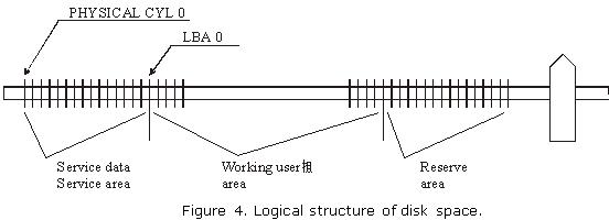
Considerable part of disk space in modern drives is hidden from users; it contains service data and an area reserved for substitution instead of defective sectors in a HDD. In normal operation mode it is accessible by drive microcontroller only. Users may access the working area frequently called logical disk space and it is exactly the same capacity as the value indicated in the characteristics of a certain model. Access to the working area represented by a continuous chain of logical sectors is performed in LBA notation from 0 to N. Connection between the logical disk space and physical disk format is established through a special program, i.e. a translator, which takes into account physical format, zone allocation as well as defective sectors and tracks to be skipped during operation.

 Access to firmware zone is possible only in a special drive operation mode, i.e. factory mode. A drive is switched into that mode by a key command opening access to an additional set of factory commands. Those commands are used for such operations as reading/writing of firmware zone sectors, obtaining a map with locations of modules and tables in firmware zone, access to zone allocation table, conversion of LBA into PCHS and vice versa, launch of low-level format, reading/writing to/from Flash ROM and some other actions.

 In the process of HDD design developers define firmware data required for drive operation as well as the number of cylinders occupied by firmware; therefore zero logical cylinder is the first free cylinder following the last cylinder occupied by firmware area. (See figure 4.) The structure of disk space may vary with different HDD models.

 Figure 4. Logical structure of disk space.

Read More

Two mechanisms of defect relocation

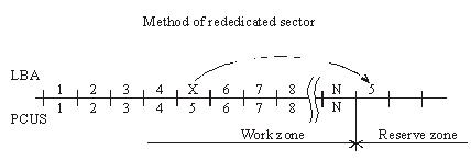
When the substitution (Assign) mechanism is used in a drive the latter records to the ID field of a BAD sector the flag of the relocated sector and writes to the data field the number of the reserved sector, i.e. the one, which should be accessed for data recording or reading. As a rule, it is the first available sector after user data area. (figure 2.).

Figure 2. Method of rededicated sector.
During data read/write operations accessing the defective sector drive controller will read the flag and assigned address and reposition the heads to the reserved zone in order to perform reading/writing from/to a good sector. Defective sectors in that case will disappear, but the drive will perform positioning to the reserved area each time it has to address a defective sector. The procedure is accompanied with clicking sounds and slight slow-down. The “Assign” procedure allows relocation only for defects in data fields. Errors pertaining to corruption of ID fields or servo fields cannot be relocated using the “Assign” method.

Another mechanism used for hiding defective sectors at manufacturing factories is skipping of defective sectors. When that method is used, the defective sector is skipped, its number is assigned to the following sector (and so on), and the last sector is shifted to the reserved zone. (figure 3.).

Figure 3. Method of missing sector.
Such method of sector hiding disrupts the continuous integrity of low-level format; the system of LBA conversion to PCHS should also take into account BAD sectors while skipping them. Therefore the method requires obligatory recalculation of translator tables and low-level formatting making it impossible to preserve user data if the method is employed. Exactly for that reason the said method of relocation is applied only in special factory mode of drive operation. It is used in the FUJFMT.EXE utility designed for relocation of defects in FUJITSU drives.

Read More

Firmware data (service information)

Firmware data is necessary for functioning of internal HDD circuits and as a rule it remains hidden from users.

Firmware data can be subdivided into the following types:
 

Servo information or servo fields;
 Low-level format;
 Resident firmware microcode (operational programs);
 Configuration tables and settings;
 Tables of defects.

 
Servo fields are necessary for operation of a servo system used by the driving assembly of magnetic heads in a HDD; they serve for heads’ positioning and keeping them precisely over a defined track. Servo fields are recorded during the manufacturing process to an already assembled HDA through special service openings in its case. The openings are subsequently closed with sticky labels that read: Warning! DO NOT OPEN. The recording is actually performed using drive’s own heads in a special high-precision instrument – servo writer.  Relocation of heads’ positioner is achieved through a motion of a special pusher of the servo writer using steady steps much smaller than the intervals between tracks.

 Firmware (microcode) of the control microprocessor is a collection of programs required for operation of HDD components. Here belong the programs used for initial diagnostics, control of spindle motor rotation, data exchange with disk controller, buffer RAM, etc. In most HDD models firmware microcode is stored within internal microcontroller ROM; some models employ external Flash ROM. In some HDD models a part of firmware programs is recorded to magnetic disk in a special firmware zone while ROM contains the programs used for initialization, and positioning together with primary loader reading the firmware data from magnetic disk to RAM. Since actual firmware modules are first loaded to RAM before execution they have been called resident modules.

 Manufacturers of hard drives record some firmware portions on disk surface not only for purposes of ROM space saving, but also to enable its easy replacement if the manufacturing process or drive operation reveal any errors in a microcode. Internet pages of most manufacturers contain links to utilities used for such updates. Overwriting disk firmware is much easier than unsoldering of hard-programmed microcontrollers. We can remember how Western Digital had to recall a large number of its drives back to factory several years ago…

 Low-level format. Track beginning is identified by an index pulse. Each track is subdivided into data sectors and servo fields. Format of each sector consists of an ID field, data field, synchronization zones and spaces. The beginning of each sector contains a synchronization zone used for phasing and synchronization of data strobe. ID field contains an address marker, physical sector address, flag byte and CRC bytes.

 Format without identifiers has become popular recently. When manufacturers employ such method of data placement along a track ID fields are not used at all (thus increasing available drive capacity). Instead they use a system of servo fields directing to physical sectors on a track. At that reading/writing of all sectors on a track is performed simultaneously (in one disk revolution) to/from RAM containing an image of the read/written track. Thus for reading just one sector a drive copies a whole track to RAM and reading of all subsequent sectors (if necessary) is performed from drive RAM instead of disk surface. Identical operations are performed during recording. During sector recording a drive reads a track, modifies it in RAM and writes the whole track back to disk.

 Configuration tables and settings of hard drives contain information about logical and physical structure of disk space. Those tables enable PCBs, which are identical for the whole drive family, to self-adjust for a certain drive model. As a matter of fact, during design of a certain model like, for example, a 80 Gb drive based on two disks it allows to produce automatically a “half-size” model with 40 Gb capacity based on one disk and “quarter-size” model with 20 Gb capacity based on one side only. Thus a manufacturer can offer a greater number of models with varied capacity for the market without considerable R&D expenses. Besides, junior models can use disks, which for some reasons are unsuitable for full-size models. E.g. “half-size” models can successfully use magnetic disks with defects on one of their surfaces, etc.

 Tables of defects. Modern technology of magnetic disks production does not allow their defect-free manufacture. Heterogeneity of media material, polishing defects, admixtures during magnetic layer application, etc. result in appearance of areas, where data recording or reading end in errors.

 Earlier drives with ST506/412 interface displayed the table of defective tracks as a label on HDA case and any drive had some reserved space, e.g. HDD ST225 (20 Mb) had actual capacity of 21,5 Mb, i.e. 1,5 Mb extra were allocated for defective sectors and tracks. Modern HDDs also have extra capacity, but it is hidden from users and only drive microcontroller can access it. A portion of that extra space is allocated to HDD firmware, configuration tables, S.M.A.R.T. counters, factory information about a HDD, tables of defects, etc. The remaining part is held in reserve for substitution of defective sectors with the reserved ones.

 Tables of defects are filled by the manufacturer during internal factory testing. Numbers of all discovered BAD sectors are added into a table. Such procedure is called updating (relocation) of defects (UPDATE DEFECT). After that if a defective sector is addressed during work with a HDD, the drive itself will redirect the request to a reserved sector. Therefore all modern drives newly arriving from the manufacturing factories have no defective sectors.

 Most HDD models have two tables of defects: Primary or P-List and Grown or G-List. Primary table is filled at the factory during internal testing – SELFSCAN (intelligent burn-in). Grown list is not filled at the factory; it is designed for addition of defects which appear during drive operation. To enable that functionality, the list of user commands practically in all HDDs contains the “assign” command replacing a defective sector with a reserved one. The command is used by numerous test utilities including those recommended by the manufacturers for operations over drives with BAD sectors. Western Digital drives have a Data Lifeguard system, which performs automatic substitution of defective sectors while a drive is idle. In order to perform the procedure, a drive self-tests its surfaces and transfers user data to a reserved sector marking at that defective sector as BAD; the mechanism of defect relocation is identical to the “assign” command. Manufacturers of Fujitsu, Quantum, Maxtor, and IBM drives implemented a mechanism of automatic defect relocation during the recording process. Thus if data is recorded to a defective sector, a drive itself will redirect such request to the reserved zone marking at that the defective sector as BAD and adding its number to G-List. Among specialized utilities used for relocation of BAD sectors we can note FUJFMT.EXE for Fujitsu drive, WDDIAG.EXE for Western Digital drives, ShDiag.exe offered by Samsung, etc.

Read More

Modern Hard disk drive

Introduction
Brief architecture description, the main problems of modern hard disk drives, methods of HDD servicing and repair of simple malfunctions, SMART, passwords. The article is intended for data recovery specialists, technicians servicing computer equipment, network administrators and experienced users.

Drive construction
 A drive consists of a mechanical part – head-and-disk assembly (HDA) and a printed circuit board (PCB). HDA acts as a case for all mechanical parts of a hard drive and contains one more chip performing the functions of a preamplifier/commutator. A PCB consists of several chips which control the mechanical parts, encode/decode data on magnetic surfaces and transfer the data through an external interface. PCBs are located outside HDA, in its lower part as a rule. In some hard drives, like the well-known Seagate Barracuda series, the controller has an additional metal cover protecting the electronic components from damage.

Mechanics
 The whole construction is based on the drive case protecting sensitive mechanical parts from environmental influence. Inside it is filled with dust-free air though the air is not specifically purified; instead the assembly of the mechanical part is performed in a special workshop where air contains less than one hundred dust particles per cubic meter, i.e. in the so-called “class 100 clean room”.

 HDA case has an opening blocked by a tight air filter. It is used to align air pressure inside the HDD and outside. Unfortunately, if a drive falls into water, the latter penetrates the inner space through that opening.  Rotation of disks creates air flow circulating inside the case and constantly passes through one more filter separating dust if it somehow appears inside.

 Drive case accommodates a pack of magnetic disks driven by a spindle motor, magnetic heads with their positioning system and a preamplifier/commutator enhancing the signal from the heads and switching between them.

 A magnetic disk is a circular aluminum (rarely ceramic or made of special glass) plate with surface polished in accordance with the highest  precision class for the sole exception of the parking zone, if it is present. In fact, high precision of disk surfaces and the heads causes them to “stick” to each other because of molecular attraction forces. To prevent that effect, manufacturers use special laser serrations in the zone of contact between drive heads and disks.

 The disks demonstrate specific magnetic properties owing to their chrome oxide based coating (magnetically active substance) or cobalt layer applied using vacuum deposition. Such coating is characterized by high hardness and much greater wear resistance compared to previous models coated with a layer of soft varnish based on ferric oxides which could be easily damaged unlike modern coatings.

 The disks are rotated by a special 3-phase electric motor. The stationary part contains three windings connected according to the “star” scheme, with a tap in the middle, and the rotating part is a permanent sectional magnet made of rare-earth metals. The requirement of beat reduction and high rotational speed values force the manufacturers to use special bearings in the spindle motor; these can be either ball bearings or improved fluid bearings (using special oil dampening impact loads and thus increasing motor durability). Fluid bearings are characterized by a lower noise level and produce practically no heat during operation. The number of revolutions per minute in modern IDE drives is equal to 5400 RPM or 7200 RPM; for modern SCSI drives it is 10000 RPM or 15000 RPM.

 A magnetic head is also a sophisticated construction composed of numerous details. Those details are so small that they are manufactured using photolithography method just like chips. Working surface of the head’s ceramic case is polished with the same precision as the disk itself. Heads’ actuator is a flat solenoid coil of copper wire suspended between the poles of a permanent magnet and fixed at one end of a lever rotating around a bearing. The other end of the lever is connected to a bracket carrying magnetic heads. The bracket is spring-loaded with a certain effort which allows the heads to “fly” at a definite height above the disk surface; the said height is usually equal to tenths of micron.

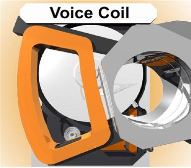
 The whole transport system moving the heads’ pack has been called Voice Coil by analogy with a loud-speaker cone. Its functional principle is similar to that of a common dynamic loud-speaker (i.e. copper coil in static magnetic field). Positioner’s coil is surrounded by a stator acting as a permanent magnet. When electric current of certain voltage and polarity appears in the coil the positioner starts turning to the corresponding side with respective acceleration; thus dynamic modification of current properties in coil allows positioning of magnetic heads to any location above disk surface.

 Drive heads are fixed when a drive is powered-off (in the parking zone) with special latches. Magnetic and pneumatic latches are two most widely used types. A magnetic latch is a small permanent magnet fixed within drive case and attracting ferrous lug on the voice coil in the heads’ parking position. Pneumatic latch (or air lock) also fixes a positioner in the parking zone preventing its further movement. When the magnetic disks begin rotation the air flow thus generated deflects the “sail” of an air latch and unblocks the positioning system.

 The electronic components inside HDA are limited to the preamplifier/commutator for the signal received from drive heads. It is located closer to the heads to minimize interference of external noise, right over the flexible cable from the heads to drive’s electronics. The same cable is connected to the voice coil and, sometimes, to the spindle motor; however, in most cases power supply of the spindle motor is implemented via a separate cable.

 A HDA is usually linked to the PCB with two connectors. One of them is a three-phase center-tapped connector for the spindle motor while the other delivers signals from the preamplifier/commutator and voice coil.

Printed circuit board
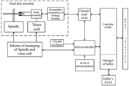
 The circuit design of modern drives is characterized by the use of a few highly-integrated chips; their block diagram is represented in figure 1.
 
 Figure1. Circuit design of modern drives

 As one can see in the picture, the whole layout is based upon four chips:
system controller chip including the read/write channel, disk controller and RISC control processor (microcontroller);
Flash ROM chip containing drive firmware;
chip controlling the spindle motor and voice coil;
ROM chip used as a cache buffer.

 Further increase of integration is impossible due to some basic differences in the operational modes of the above functional parts.

 The first system controller used in hard drives was a chip manufactured by Cirrus Logic. Its obvious breakthrough was manifested in the read/write channel, processor and disk controller integrated within one chip; however insufficiently developed methods of using such a microcircuit caused frequent malfunctions of  Fujitsu drives belonging to series  MPF3xxxAT and MPG.

 A microcontroller has RISC architecture. As soon as power supply is switched on after the /RESET interface signal the drive reset circuit sends a RESET signal to microcontroller which executes its program from ROM running self-diagnostics, cleaning the working data area in memory and programming disk controller and all programmable chips connected to the internal data bus of an HDD. Then microcontroller polls internal signals used during drive operation and if it detects no emergency alerts, it starts the spindle motor. The next stage of firmware operation is internal testing of an HDD checking data buffer RAM, disk microcontroller and the status of microcontroller signals input from its port. Then the microcontroller begins analyzing the frequency of pulses waiting until the spindle motor reaches defined rotational speed. As soon as the necessary speed is reached, the controller begins to manipulate the positioning circuit and disk controller moving the magnetic heads to the area containing recorded firmware data and transfers it to buffer RAM for further operation. Then the microcontroller switches to readiness and awaits commands from HOST. In that mode a command received from the central processor initiates a whole chain of actions performed by all the electronic components in a HDD.

 HDD read/write channel consists of a preamplifier/commutator (located inside HDA), read circuit, write circuit and a synchronizing clock.

 Drive preamplifier has several channels, each being connected to its respective head. The channels are switched by signals from the drive’s microprocessor. Preamplifier also contains a recording current switch and recording error sensor, which emits an error signal if a short circuit or break occurs in a magnetic head.

 Integrated reading/writing channel operating in the recording mode receives data from disk controller simultaneously with the recording clock frequency, performs data encoding, precompensation and transfers the data to preamplifier for writing to a disk. In the reading mode signal from preamplifier/commutator is transmitted to the automatic control circuit and then passes a programmable filter, adaptive compensatory circuit and pulse detector while being converted into data pulses sent to the disk controller for decoding and transfer through an external interface.
 Disk controller is the most complicated drive component which determines the speed of data exchange between a HDD and HOST.

 Disk controller has four ports used for connection to a HOST, microcontroller, buffer RAM and data exchange channel between it and HDD. Disk controller is an automatic device driven by microcontroller; from HOST side only standard registers of task file are accessible. Disk controller is programmed at the initialization stage by microcontroller, during the procedure it sets up the data encoding methods, selects the polynomial method of error correction, defines flexible or hard partitioning into sectors, etc.

 Buffer manager is a functional part of disk controller governing the operations of buffer RAM. The capacity of the latter ranges in modern HDDs from 512 Kb to 8 Mb. Buffer manager splits the whole buffer RAM into separate sectioned buffers. Special registers accessible from microcontroller contain the initial addresses of those sectioned buffers. When HOST exchanges data with one of the buffers the read/write channel can exchange data with another buffer sector. Thus the system achieves multisequencing for the processes of data reading/writing from/to disk and data exchange with HOST.

 Spindle motor controller regulates the motion of a 3-phase motor. It is programmed by the drive microcontroller. There are three control modes of spindle motor operation: the start mode, acceleration mode and stable rotation mode. Let us review the start mode. At power-up a reset signal is sent to the control microprocessor which performs initialization programming internal registers of spindle motor controller for a start. Drive controller generates phase switching signals; the spindle motor at that rotates at low speed generating self-induced electromotive force. Drive controller detects EMF and notifies the microprocessor which uses that signal for rotation control. In the acceleration mode microprocessor speeds-up phase switching and measures the rotational speed of the spindle motor until the speed reaches its rated value. As soon as the rated rotational speed is reached the controller introduces stable rotational mode. In that mode microprocessor calculates the time required for one revolution of the spindle motor based on the phase signal and adjusts the rotational speed accordingly. After relocation of magnetic heads from the parking zone the drive electronics begins tracking the stability of rotation using servo marks.

 Voice coil controller generates the control current moving drive positioner and stabilizing it over a defined track. Current value is calculated by microcontroller on the basis of digital error signal for head position relatively to a track (Position Error Signal or PES).  Current value in digital form is transmitted to CPU, the analogous signal thus received is enhanced and supplied to the voice coil.

Read More

Hard Disk Details(11)

Random Notes and Ideas For Data Recovery

    1. Drive goes to sleep, replace the board live
    2. Partitions start on Cylinder Boundaries
    3. Hard Drives have a Safe Mode
    4. You can fix LaCie problems with a Mac mounting them in the system
    5. Drives that you plug in that cause windows to Crash – Use Ubuntu to Read Files
    6. When problems with MFT then retry smaller blocks
    7. If drive parts are good then rewriting the SA area is the part that needs repairing
    8. SA Code can be replaced to do data destruction or encryption
    9. If you are thinking of a hard drive as 0’s 1’s then you are wrong. The equipment interprets signals to make the representation of 0s or 1s. Designers have taken into account the signal distortion and interface problems to make the work
    10. Remove a chip from the PCB and re-solder the chip onto a good board to fix specific problems with chips that are burned, cracked, etc
    11. Soft resets on SATA also need to do a hard reset the controller as it cannot be reset any other way like the bus is reset in a PCI or ATA
    12. ATA-3 Spec – hard drive read without retry was disabled and now is internal on the drive
    13. Seagate Drives use a serial interface of which you can find online. It will show you stats on the drive. If you see FFFF mask FFFF mask it is a head error
    14. If a drive is read with a standard read then it does not need to be read again but it might be good to use ECC to compare in a later pass
    15. Force the drive to use PIO mode instead of DMA/UDMA modes. Some hard drive failures cause the drive to fail reading UDMA but might still work in PIO
    16. Powers on good drive, while board is still in use move it to a new drive. Wrong defect tables and can be cleared
    17. If the platters are misaligned you can write data over the servo wedge and thereby destroying any chance that you can ever read the data
    18. As the thermal heat increases stability of the bits drop rapidly and with the addition of Areal density – degradation is much higher. There are fewer atoms in each bit to retain the bit orientation. Currently the drive will test for decay and if detected will automatically rewrite the data it detects
    19. Hard drives stored in heat for long term storage is extremely bad
    20. Adaptec ATA Raid 1200A Controller in combination with MHDD is great for recovery software.
    21. To determine if there is an HPA – Look at the LBA Maximum and if it is equal to Maximum Native LBA then there is no HPA
    22. Partitions created using standard disk partitioning tools, fdisk, Windows Disk Management, Partition Magic, will all be cylinder aligned. You only have to scan cylinder boundaries for partitions. Dynamic disks do not use partition tables, they use LDM which is at the end of the disk and needs to be done backwards. It uses one single partition occupying the entire disk minus one cylinder. When volumes are added or deleted the partition table is not updated. There are only 4 partitions possible with the standard Windows tools
    23. All partition table signatures end in 55 AA – if this is gone the OS will regard this as not existing. 80 is active 0B fat32 0F extended
    24. Everything in NTFS is a file – $boot
    25. Sector is the smallest addressable unit on the disk. You can read more than one sector but you cannot read less
    26. If doing a head replacement try straws for head stack replacements around the heads to keep them protected. Cut off a small piece of a drinking straw and place it over the head area of each and every head
    27. Even when the lower part of a head stack does not have heads they are still numbered.
    28. Increasing numbers of drive have no chance for parts replacement due to changes in the hardware
    29. Some drives store the lists in the NV Ram on the PCB. The table on one drive will not match the table on another drive and are unique. That might cause the same logical blocks to be mapped to different physical blocks on different hard drives. It is possible to have a swapped board cause a space on the hard drive to be overwritten due to the mapping problem.
Read More

Hard Disk Details(10)

Matching Serial Numbers on Hard Drives
This link is where I keep track of documentation on how each hard drive needs to be matched for a working donor drive.  I get this any where I can, use it if you can, and if you happen to find something out please let me know so I can add it to the collection!

NOTES:
Drives with the same model number can still have different numbers of heads, therefore the board is different. It is possible to identify the number of heads in a drive: Maxtor,Quantum, Seagate from the serial numbers:

REFIRBUSHED DRIVES
REFIRBUSHIED drives cannot be used as a donor drive. Head 0 is the bottom head and could be bad. And substandard parts are often installed. It is very difficult to match a refirb drive to a good drive with the same problems. This also makes it difficult to make repair a refirb drive.

QUANTUM
Quantum – the third number in the serial number shows the headsQuantum = HA code must match

SEAGATE
Seagate – the third SYMBOL in serial number represents the heads. Seagate’s sometimes have extra heads and when one is refurbished it is possible to turn off a bad head and turn on an alternate one and then the firmware number revision might change.

FUJITSU
Fujtsu needs the first xx-Xxxx to match

IBM and HITACHI DRIVES – Usually the same driveIBM MLC codes have to match

HITACHI
Hitachi ATMR 80gigs fails mostHitachi 3.5 – Firmware code needs to matchHitachi 2.5 – PCB rev has to match

WESTERN DIGITAL DRIVES
DCM codes for the (5th??? And) 6th numbers must match.No Western Digital drives with the letter R in the code. EB and BB models.Western Digital Drives EB and BB have the head stack affixed from the lid. Western Digital the sixth char in the model is the cache. U = 2meg V=8meg

SAMSUNG
Samsung the 4th Char in the alpha code on the label on the rear side needs to matchSamsung the 7th char in the model is the size of the buffer H=8megs

MAXTOR DRIVES
The second number of the serial number represents the number of heads Maxtor needs the 2nd and 3rd char to match:

Hi you all, this is the answer I received directly from Maxtor
Dear Mr. Robert,… here is the paragraph that deals with your model type (DiamondMax Plus 9):
For the following Maxtor hard drive models: Fireball 3, DiamondMax 16, DiamondMax Plus 8, DiamondMax Plus 9, Diamond Max 10 and all MaxLine products there is also a GTLA Number on the model (next to barcode on the bottom of the drive). Format 1Y222J2223322. 1, 2 and 3 stand for numbers, Y and J for letters. The numbers 1 and 3 as well as the letter Y need to be identical to be able to replace the PCB on these drives.  This number can be found on the large sticker on the top of the drive.

Unfortunately we cannot give you any more information than this. Any of your DiamondMax Plus 9 drives could possibly have a matching PCB, however it is most likely to be an older one as the drive in question is almost 3 years old.

Kind regards,
Gisela Schubert Technical Support
Maxtor Ireland Ltd.

copied from: http://forum.hddguru.com/howto-how-to-replace-maxtor-calypso-iii-board-vt5977.html

Serial Number on Hard Drive
The boot sector in the FAT32 partition

The boot sector in the FAT partition
The data contained in the boot sector after the OEM name string is referred to as the BIOS parameter block or BPB

Read More

Hard Disk Details(9)

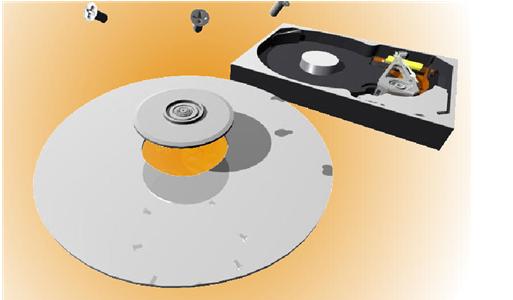
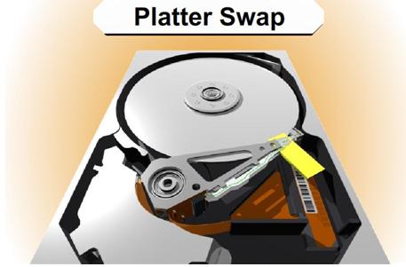
Slide 4500:  Doing a Platter Swap for a Single Platter

List of items needed:
The first step is to get a hard drive as close to identical as the bad drive you have that is a working drive. At the bottom of this paper you will find help about matching hard drives and serial numbers.
You need a clean area to work on with as little dust floating around as possible.
You will need about 1 hour to do this carefully
A screwdriver set with T3-T8.  These are my favorite http://www.wihatools.com/200seri/278serie.htm
Post-it Notes
Other tools depending on the drive
Anti-Static Gloves ($5 at the local store)
Patience

Just move the head as careful as you can to get it out of the way

NOTE:
This is a fairly simple task compared to a head swap. The hardest part is again getting the heads aligned and back on the platter correctly.
If you have a ramp on your drive it is fairly simple to get the head moved out of the way enough to get the platter in position.

Remove the platter from the good drive.

NOTE:
I usually will try to put a screwdriver in the shaft just to the edge of the center of the platter and turn the drive just enough to get the platter to slide on to the screw driver. I will do the same for the bad drive to move the platter to the good drive.

The platter will most likely never be used again so just get it out however you can without affecting the rest of the drive.

Again I use the Post-it notes in the shape of a V to get the heads back on the platter as I did in the head replacement.

Be very careful to keep the orientation in the same direction to so that the platter will be in the correct location when you put the platter back on the new drive.

Slide TBD: Doing a Platter Swap for a Multi-Platter

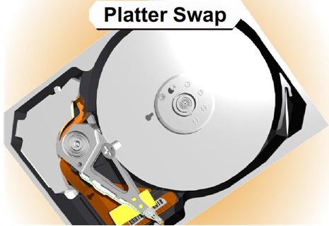
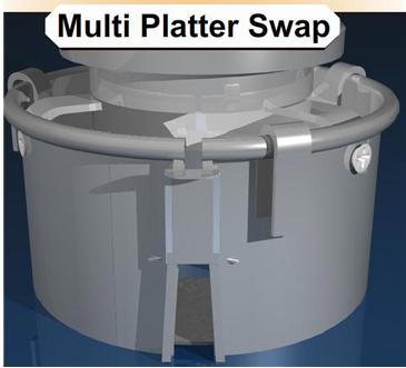
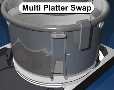
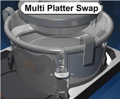
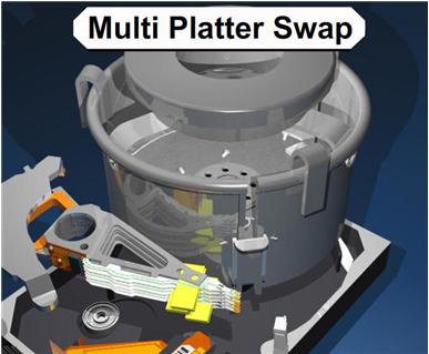
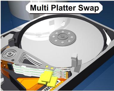
In order to do a Multi-Platter replacement you will need a special tool. If you have more than one platter and you take out the platters and any one of them turns at all, you will never get them aligned again or be able to read the data. This is because the data is written in a cylinder. Since the data is in a cylinder you must have the exact same alignment of the platters in order to move them to a new hard drive.

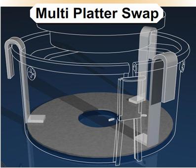
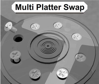
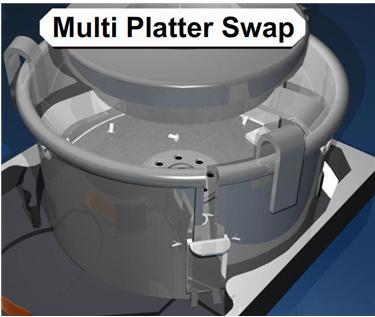
There is a special tool called a Platter Replacement Stand. You can get one at SalvationData.com  http://www.salvationdata.com for around $250 plus postage. It is a really heavy stand and weighs about 10 pounds.  The platter replacement tool is what you really need and it looks a lot like a coffee can with a slit in the side.  Once you have moved your heads out of the way, this can sits down around all the platters and you can push down on a piece of metal mounted in the slit to tighten it around the platters.  It also has a lid inside that sits on the top ring of the platters that will hold the screws and keep them from rolling around all over the platters.

The pressure from the “coffee can” will hold all the platters together; however you still have to be really careful about taking it out and turning it. It should go straight from one hard drive to the other as quickly as possible with as little movement as possible.

This is the best possible way to keep the drive platters lined up.

You will still reassemble the drive just like you do in a head stack replacement or a single platter replacement. The only difference is using this device to move the platters.

The plate inside the tool holds the screws so that they do not scratch the platter.

Realign the heads.

Read More

Hard Disk Details(8)

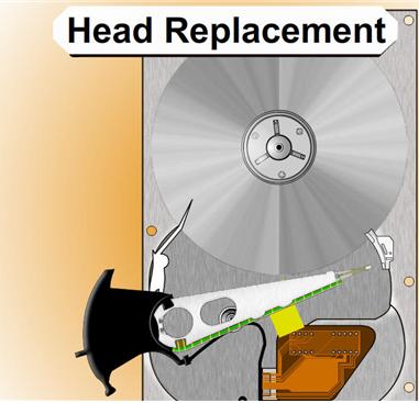
Slide 4259: Head Replacement Section
This is the only section from last year I kept and it is because this is directly related to fixing this click of death problem.

NOTE: If there is only one platter it might be easier to move the platter than to move the assembly. You have to make that choice.

List of items needed:
The first step is to get a hard drive as close to identical as the bad drive you have that is a working drive. At the bottom of this paper you will find help about matching hard drives and serial numbers.
You need a clean area to work on with as little dust floating around as possible.
You will need about 3 hours to do this carefully
A screwdriver set with T3-T8.  These are my favorite http://www.wihatools.com/200seri/278serie.htm
Post-it Notes
Other tools depending on the drive
Patience

Process for Head Replacement:
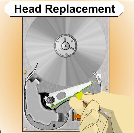
1.  You will need to disassemble the heads and other components from the drive to clear the room for the head and components.

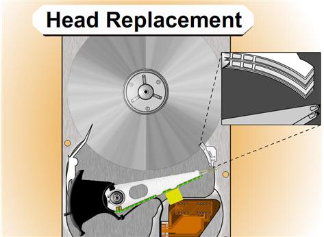
2.    Disassemble the new hard drive, and carefully use folded paper to move the heads apart and to keep them apart as much as possible.

NOTE: If you are going to move the heads off of a drive platter you should always spin the motor in the direction away from the heads and the arm while you are moving the actuator arm to get the heads off. Move with care.

If you are storing the heads or going to put them down, you can try cutting sections of a drinking straw around the head itself. If the drive has a ramp it is very useful to help line up the heads to take them off and to put them back on.

*** There is often a screw under the assembly of the actuator arm that needs to be removed to move the heads.

3.    Carefully lift the assembly out of the drive and move it to the bad drive and reassemble. It will take about two hours to assemble correctly if you take your time. Do everything you can to get the heads lined up again.

NOTE: It is helpful to fold a piece of post-it notes in a V shape and to make the V towards the platters and the heads on each side of the V.  You can get the paper to slide onto the platter and turn the platters with a screwdriver while you gently move the heads back into place.

You must get them lined up and review it before you turn the drive back on or the heads may slide into place and hit the edge of the platter ripping them off and scratching the platter.  It is good to practice with another drive you do not care about before doing this.

Read More

Hard Disk Details(7)

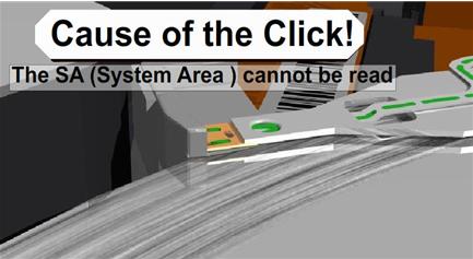
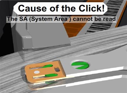
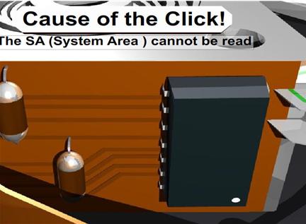
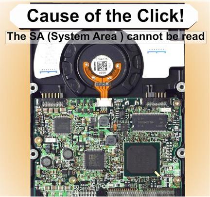
Slide 3791: The cause of the click is from four possible areas, all resulting in the SA not being able to be read.

1.    System Area of the drive cannot be read because the platter is scratched.

2.    The head itself has a problem and cannot read the SA area.

3.    Preamp on Actuator to the Head has gone bad and is not passing the correct signal to the electronics

4.   The firmware on the board is damaged and does not initialize. This is sometimes caused by static electricity walking across the carpet to install the drives, or there is a short on the board, and additionally I see where someone has allowed the board on the bottom of the drive to touch metal cause it to burn.

All will result in the same problem and will sound like the Click of Death. Recovery Software will not help you correct any of these until after you have repaired the drive and it is running again.

Correcting Problems
Now we move on to some of the things you can do about it on your own.  The click of death is a very difficult problem to solve and in some cases will not be able to be solved especially without some very high end and expensive equipment. But I will tell you what I have been able to fix without that equipment.

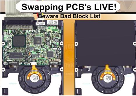
Slide 4009: Swapping the PCB (printed circuit board) Live to get around a SA area that cannot be read.

I have done this process several times successfully. It is not perfect but it is a possible chance you will have to recover your data. The first step is to get a hard drive as close to identical as the bad drive you have that is a working drive. At the bottom of this paper you will find help about matching hard drives and serial numbers. If the System Area is badly damaged or corrupt and for some reason the drive will not read the System Area you can attempt to do a live swap. What this means is that you can hook up the good drive, then you use software or windows and tell the drive to go to sleep.  This will cause the drive to spin down but will still be live and powered up and mounted.  Once the drive goes to sleep and the drive stops spinning you can unscrew the board, carefully so as not to let the screws roll around on the board, and disconnect the board and connect it to the bad drive. I suggest that once you do this, you go after the files you need very quickly. It’s possibly you will be able to make an image of the drive.  Keep in mind, that whatever bad blocks that the drive had assigned to the other drive will be bad here as well.  You could try to use some software to clear bad blocks before attempting this, however I don’t suggest it in most cases. That is because it is one more possible item that might cause failure. I would prefer to use the drive that was working and lose a few blocks. After you get what you can then you can attempt to make changes and go back for more data. This is a concept that works about 25% of the time.

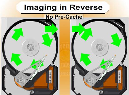
Slide 4199: Imaging in Reverse

In dealing with damaged hard drives, I have run into many problems with cache memory on the drive. The problems will often show up as timeouts or ECC failures as well. For example, I try to read from a drive with16 megs of ram for cache and receive errors but the drive is otherwise appears ok. If there is an error 16 megs away from the sector I am reading my drive will die. As of now there is no way to turn off this cache.  However, if you can image your drive backwards there is no cache. Memory on a drive only caches data forward. There are only three ways I know of to image a drive backwards. The first is free, and it is to use dd_rescue. dd_rescue has a special setting for imaging a drive backwards. There is also a special script for dd_rhelp to control dd_rescue for the purpose of data recovery. You can use this on Linux and it works on drives regardless of the operating system on the drive you are recovering from. Typically you will start at the MaxLBA number and work backwards down to 0 LBA. It works quite well and will work on a surprising number of drives that cannot be read any other way. Your other two choices are Media Tools Pro from RecoverSoft (http://www.recoversoft.com/) for Windows, which is about $400, or a piece of hardware which is extremely efficient at doing this type of recovery called Deepspar Disk Imager (http://www.deepspar.com/products-ds-disk-imager.html), which will cost between $3000 and $4000 depending on configuration. But you should contact each of these vendors for pricing, or use the free option!

Read More

Hard Disk Details(6)

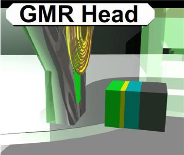
Slide 2840: The GMR (giant magnetoresistive) head is the current head used on most hard drives. This head uses high end physics I do not claim to understand. The only major difference is the way the head has been changed to read perpendicular. The GMR head has four layers, a sensing layer, a conducting layer, a pinned layer and an exchange layer.  It was discovered that if you took two magnetic layers and aligned them opposite each other with a soft layer between them that the magnetic force would align themselves in parallel. When a bit of data passes under the heads the electrons bounce around in the layers causing the pinned layer to spin.

For more info, read http://www.hitachigst.com/hdd/technolo/gmr/gmr.htm
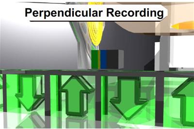
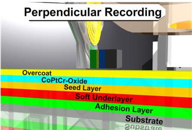
Slide 2865: Hard drives have switched to Perpendicular Recording.  I talked about the changes and previous versions last year and you can reference that speech for more info. The biggest change switching to perpendicular is that the data is written up and down instead of longitudinal. Because of this, changes had to be made to the platter so it would not interfere with reading and writing.

Slide 2885: The coatings have changed and  the substrate on the bottom (the platter itself) was the biggest change. Almost every platter has converted to a glass ceramic platter.  What this means to you in data recovery is that it is obvious when a scratch occurs. In most cases you will be able to see though the platter. Sometimes the rings that are created by the scratch are so smooth that they look like they are supposed to be there.  I assure you that they are not.  It should be silver from one edge to the other with no rings at all.  So if you see a ring, in most cases the game is over or your recovery just got a lot harder.

Slide 3000:  The data structure that is written to the sectors is important to understand if you are using any diagnostic software.  Many of them use common nomenclature to discuss the types of errors.

Common Error Codes and Diagnostic Info from Most High End Software:
BSY – drive busy
DRDY – Drive ready to accept commands
ERR – The Last Result was an Error
DREQ -exchange data with host
UNCR-Uncorrectable Error
WRFT – Write Fault
AMNF-Address Marker Not Found
IDNF- Sector ID Not Found
ABRT- Command Aborted
TONF – Track 0 not found

You will see the error codes here in almost all data recovery and diagnostic software.  This particular block of data (slide 3259) is one single sector. It contains a 512 byte block of data.  This is how on sector looks to every hard drive regardless of your operating system.

I could not possibly explain every error you will see, but I can give you the basics of the most common you will see doing diagnostics.

 IDNF is the Address not found. If the sector that holds this information is corrupt there is no way for the hard drive to locate this sector and it will return the result IDNF.

 AMNF is the Address Marker Not Found. This is similar to the IDNF but relates to the data. If there is an error and this marker is corrupt then the data for this sector cannot be located. The data in this area is 512 bytes of user data.

 ECC is that there is a problem reading from ECC and it does not match. ECC is used to check the integrity of the data being read. When the data is read the drive calculates the ECC and compares. If there is an error the drive will retry until it cannot get a correct result and then will return the UNC error.

 UNC will happen when the data is uncorrectable data error.

 ABRT is an abort error and it will discontinue trying to read that block

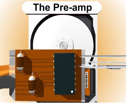
Slide 3559: The preamp is a chip that amplifies the signal coming from the heads of the drive. Since the data that is read coming from the heads is similar to a wave form from a speaker, the preamp will amplify it and send it on to the electronics for decoding. There are two types of preamps, one is soldered on, and the second is glued on.  It is often possible for a preamp to come loose due to heat expansion and not to have a good connection to the board. It is also possible for the preamp to fail. This is one of the causes of the click of death for the hard drive. It is often difficult to replace or fix this circuit and is more likely you can do a platter swap to a good drive, or replace the head stack assembly. The voice coil was mentioned in previous information at Defcon 14.

Click of Death and Hard Drives Safe Mode Notes
Errors cause the drive to constantly shutdown and recalibrate, this is a sound or movement that can usually be heard or seen and is known as the Click of Death for hard drives. If drive parts are good then rewriting the SA area is the part that needs repairing. The difficultly is in knowing if the rest of the parts are good. The SA can only be rewritten by a few devices. There are a few ways to get around this; one of the ways is a live PCB swap. Again the SA is not accessible over the interface without special tools.

Most hard drives have a specific recalibration routine they use to retry the SA area. Even though it cannot be read most drives will continue this routine.  A few drives will, after a certain number of times automatically power down.  The normal timing routine for this process is:
         Two head clicks
         power down
         two head clicks again
** Some drives will perform three head clicks before powering down.

Maxtor drives will test all heads from 0 to F; it must come out to level F, or stop the spindle. The problem of Quantum drives of all series (including last series — known as Maxtor D540X and D740X) can be detected by the specific sounds: after starting, there will be two loud clicks, then drive’s motor will increase its speed, and there will be 4 more clicks, after which the drive will become “ready”. For Western Digital a dead preamplifier is also detected by the specific sounds: after two loud clicks the drive will stop the spindle. If you have a clicking Maxtor then heads malfunctioning is characterized with a continuous clicking for over 30 seconds. Samsung drives with a dead preamplifier also click two times and then stop the spindle; however, for Samsung drives it can also mean problems with reading of the critical modules of the system area.

Hard Drives Safe Mode
Can be done by setting jumpers in case a module is damaged or some drives can detect it and go into safe mode itself. In safe mode the drive bypasses its own firmware and is waiting for firmware to be uploaded to ram. The RAM code is called the loader and will start the drive operations. It is possible for the hard drive to go into safe mode all by itself if it detects a problem. You will never know this is happening on purpose. Some software like MHDD might be able to tell you if your drive is in safe mode. You will never be able to recover data until this problem is solved and it is not running in safe mode. When it is running in safe mode it will sound like the Click of Death on most hard drives.

Diagnostic software called MHDD or Victoria
http://hddguru.com/content/en/software/2005.10.02-MHDD/

MHDD Software commands and functions:
Erase Waits:- It is better to use this for Drive Repair but it is data destructive
HPA :- Host Protected Area Functions
REMAP: – Try to recover bad sectors
Standby: – turn the motor off
PWD: – User Password INFO
Dispwd: – disable the password
Fdisk: can make one full size fat 32 drive

Read More