What is the difference between a Microsoft Basic Disk and a Dynamic Disk?

There are two different types of disk storage available to the Windows Vista, XP and 2000 environment:

  • Basic Disk Storage
  • Dynamic Disk Storage

The number of partitions (on basic disks) and volumes (on dynamic disks) that each can contain are the primary differences.  Single drive systems with one drive letter C: are typical basic disks.  A server that needs to be divided up into several parts may benefit from a dynamic disk configuration.  Some versions of Windows will convert a basic disk into a dynamic type.

Basic Disk Storage
Basic storage uses partition tables that are supported by MS-DOS, Microsoft Windows 95, Microsoft Windows 98, Microsoft Windows Millennium Edition (Me), Microsoft Windows NT, Microsoft Windows 2000, and Windows XP. A disk initialized for basic storage is called a basic disk. A basic disk contains basic volumes, such as primary partitions, extended partitions, and logical drives.

Dynamic Disk Storage
Dynamic storage is supported by both Windows 2000 and Windows XP Professional. A disk that is initialized for dynamic storage is called a dynamic disk. A dynamic disk contains dynamic volumes, such as simple volumes, spanned volumes, striped volumes, mirrored volumes, and RAID-5 volumes.

Read More

Can I use DiscWizard to setup my Seagate external hard drive?

DiscWizard DiscWizard can be used not only to format ATA and SATA drives, but external Seagate drives connected to the computer through USB, Firewire, or eSATA as well.  Though the setup procedure is almost the same as that used with internal drives, you want to be aware of a few of things:

  1. Unlike previous versions of DiscWizard, in addition to being able to use DiscWizard for Windows to set up an external hard drive, you can now also use the bootable version of DiscWizard for the same purpose.
  2. The external drive(s) can be identified by its interface type, which is listed in the “Interface” column of the Add New Disc Wizard.
  3. DiscWizard can only be used in Windows 2000, XP, and Vista.  For Windows 98 and Me, you will need to use FDISK and FORMAT instead.
  4. Because their connections have slower sustained transfer rates than internal ATA and SATA connections, partitioning and formatting USB and Firewire hard drives may take longer than usual.
  5. All other step are the same that you would see when preparing an internal hard drive.
Read More

How to Use SeaTools for DOS to Set the Drive Size

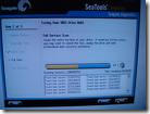
Seatools For DOS Sometimes it’s necessary to use the SeaTools for DOS software to get the drive back to its native capacity.  For example, if the drive is showing up as a smaller capacity in the BIOS (i.e. 137GB or 32GB) and it’s a computer that should support a drive that large, then this would be a time to set the drive size.

Once booted from the SeaTools for DOS disk the computer should be at screen with a license agreement.

  1. Click “I agree” to the license agreement.
  2. Now choose which drive to set the size of.  Look at the bottom portion of the window to see what drives are listed and what device number they are.  You can see what device is selected by looking in the middle of the screen.  The model number of the drive currently selected is displayed here.  If this is not the current drive click the “D – Drive” button in the upper left until you see the drive you want to test displayed in the middle of the screen.
  3. Click “C – Set Capacity” at the top of the screen.
  4. Click the “R – Reset to Maximum” button.

If you get an OK message in white in the middle of the screen then the process was successful.  Power off the computer for a few seconds and check in the BIOS to check the capacity of the drive again.

If there was a message in red, then this was an error.  Make sure the drive is connected directly to the motherboard and not to a third-party controller card.  If the drive is on a controller card then it’s possible that the set drive size command may not work.  Once it’s connected directly try to go through this procedure again.

Another option is to try a quick zero-fill from the main menu and then to try a C – Set Capacity again.

Read More

What is the CMOS memory?

CMOS Memory CMOS is an abbreviation for Complementary Metal Oxide Semiconductor. CMOS uses a complimentary arrangement of both NMOS and PMOS, negative and positive Metal Oxide transistor circuits. CMOS memory draws very little current (nano-Amps). Values stored in it can be maintained for very a long period of time while the computer is off with a rechargeable lithium battery. The CMOS memory is used to store system configuration information, such as disk drive parameters, memory configuration, and the date-time, some of which you enter in the CMOS Setup program, . It is used by the Basic Input Output System (BIOS), a program permanently stored in the flash memory on recent motherboards and in read-only memory (ROM) on older motherboards, to configure the computer. The CMOS Setup is part of the BIOS program. The CMOS memory is usually located with the real-time clock in the motherboard chipset or in a separate real-time clock chip. It is located in the chipset on most recent motherboards. For example, the CMOS memory is located in the VT82C596B Southbridge chip in the VIA MVP3C chipset on the Epox MVP3G2 Super7 Motherboard and in the AMD-756 Southbridge in the AMD-750 chipset on the MSI MS-6167 Athlon motherboard.

Read More

SCSI Levels

SCSI Levels SCSI – Small Computer System Interface

An intelligent peripheral interface characterized by its use of high level communication between devices. Communications are defined as being between an “Initiator” and a “Target”. The Initiator is normally a computer, and the Target is normally a peripheral. Data may be transferred in asynchronous (not clocked) or synchronous (clocked) mode. All messages and commands are always transferred in asynchronous mode.

This term is often used to describe the published ANSI standard now called SCSI-1 (X3.131-1986).

SCSI-2

This is a term describing the published ANSI standard (X3.131-1994). SCSI-2 was an upgrade from the original SCSI interface. Changes included faster data rates and mandated message and command structure to improve compatibility. Synchronous data transfer rate for SCSI-2 is 2.5 to 10 Mbytes/sec for an 8-bit data bus (N/ND models), and 5.0 to 20 Mbytes/sec for a 16-bit data bus (W/WC/WD/DC models).

SCSI-3

This term describes a set of related ANSI standards that are currently being developed for the SCSI bus. The SCSI-2 document is very large (400+ pages) and covers the full range of topics. SCSI-3 split this large document into a series of smaller documents, each covering a “layer” of the interface definition.

The basic layers are:

physical (connectors, pin assignments, electrical specifications)

protocol (physical layer activity is organized into bus phases, packets, etc.)

architecture (a description of how command requests are organized, queued, and responded to by any protocol)

primary commands (description of commands that must be supported by all SCSI devices)

device specific commands (commands that are specific to a particular class of devices; CD-ROMs or -WORM drives, for example)

The set of standards needed to do a SCSI-3 parallel interface disc drive implementation are:

SPI (SCSI Parallel Interface) for the physical layer
SIP (SCSI Interlocked Protocol) for the protocol layer
SAM (SCSI Architecture Model) for the architecture
SPC (SCSI Primary Commands) for the primary command set
SBC (SCSI Block Commands) for the disc drive specific command set
The SCSI-3 standards are layered in this manner to allow substitution of parts of the structure as new technology emerges. For example, a comparable set of standards for a SCSI Fiber Channel interface disc drive replaces the physical and protocol layers with new documents but uses the same documents for the other 3 layers. The main point to remember here is that the terms SCSI-2 or SCSI-3 do not imply any particular performance per se, rather they refer to the generation of documents to which a product conforms. Since the newest features are only in SCSI-3 and tend to be higher performing, SCSI-3 devices should demonstrate better performance than SCSI-2 in most cases.

SCSI FAST

This refers to timings defined in SCSI-2 for a 10 MegaTransfer/sec transfer rate. A “MegaTransfer” (MT) is a unit of measure referring to the rate of signals on the interface regardless of the width of the bus. For example, a 10 MT/sec rate on a 1 byte wide (narrow) bus results in a 10 Mbytes/sec transfer rate, but on a 2 byte (wide) bus, it results in a 20 Mbytes/sec transfer rate.

SCSI FAST-20

This refers to timings defined in SCSI-3 SPI for a 20 MT/sec transfer rate, which achieves data rates twice as fast as SCSI FAST rates. For example, a 20 MT/sec rate on a 1 byte wide (narrow) bus results in a 20 Mbytes/sec transfer rate, but on a 2 byte (wide) bus, it results in a 40 Mbytes/sec transfer rate.

SCSI FAST-40

This refers to timings being defined for a future revision of the SCSI-3 SPI that achieve 40 MT/sec, which is twice as fast as SCSI FAST-20 rates. For example, a 40 MT/sec rate on a 1 byte wide (narrow) bus results in a 40 Mbytes/sec transfer rate, but on a 2 byte (wide) bus, it results in an 80 Mbytes/sec transfer rate. For more information, see Ultra2 SCSI.

SCSI FAST-80

This refers to timings being defined for a future revision of the SCSI-3 SPI that achieve 80 MT/sec, which is twice as fast as SCSI FAST-40 rates. For example, an 80 MT/sec rate on a 1 byte wide (narrow) bus results in an 80 Mbytes/sec transfer rate, but on a 2 byte (wide) bus, it results in a 160 Mbytes/sec transfer rate.

Ultra SCSI

This is a term describing the latest published ANSI standard (X3T10/1071D rev. 6), commonly known as Fast-20. Ultra SCSI, like all synchronous transfers, is a negotiated clock rate. For more information, see The UltraSCSI Buzz.

Ultra2 SCSI

This is a term describing the latest published ANSI standard (X3T10/1071D rev. 6), commonly known as Fast-40. Ultra2 SCSI, like all synchronous transfers, is a negotiated clock rate.

SCSI Narrow

This term refers to the 1 byte wide data bus on a 50-pin parallel interface that is defined in the ANSI standard SCSI-1 (X3.131-1986).  The narrow bus consists of 8 data lines with parity, a series of control lines and the matching ground lines.  Seagate designates a narrow SCSI interface with an “n” in the model number.

image

SCSI WIDE

This term usually refers to the 2 byte wide data bus on a 68 pin parallel interface that is defined in the SCSI-3 SPI document. The term can be generically applied to any implementation wider than 1 byte, but at the time of this writing, there are no implementations wider than 2 bytes. Future implementations may include more data bytes because FAST transfer rates are giving plenty of life to 2 byte transfers until serial interfaces (like Fibre Channel or FireWire) become more popular. Seagate designates a wide SCSI interface with a “w” in the model number.

image

SCSI FAST-WIDE

This refers to a combination of a FAST transfer rate with a 2 byte wide connector, resulting in an increased data transfer rate. Wide FAST-20 (40 Mbytes/sec) products will be available in the year of this writing. Wide FAST-40 (80 Mbytes/sec) and FAST-80 (160 Mbytes/sec) products will be available in the near future.

Differential or High Voltage Differential (HVD)

Differential (D, ND, WD, WDC) is a logic signal system used in some SCSI drives. It uses a paired plus and minus signal level to reduce the effects of noise on the SCSI bus. Any noise injected into the signal would be present in both a plus and minus state, thereby being canceled. Seagate designates a differential (high voltage) SCSI interface with a “d” in the model number.

Due to changing definitions, Differential is now often referred to as High Voltage Differential (HVD).

Low Voltage Differential (LVD)

Low Voltage Differential is a differential logic scheme using lower voltage levels than HVD. For more information, see Ultra2 SCSI. Seagate designates low voltage differential SCSI interface with an “l” in the model number.

Fibre Channel Arbitrated Loop (FCAL)

This is the formal name for the Fibre Channel system used by SCSI. It is more commonly known as Fibre Channel SCSI. The loop part of the name refers to the way the system is connected as one large ring. Because of the loop characteristics, this interface has more in common with local area networks than with parallel SCSI.

Fibre Channel SCSI

This refers to products with fibre channel physical and protocol layers using the SCSI command set. The Fibre Channel interface is completely different from parallel SCSI in that it is a serial interface, meaning command and data information is transmitted on one signal stream organized into packets. The fibre may be either a copper coaxial cable or a fiber optic cable. The signal on the first implementation of fibre channel uses a 1 GHz rate, thereby achieving 100 Mbytes/sec over the cable. Fibre channel also implements increased software control of configuration and pushes the total device count on the bus to 126 IDs, as opposed to only 8 or 16 on a parallel bus. For more information, see our Technology Paper on Fibre Channel. Seagate designates a fiber channel SCSI interface with an “fc” in the model number.

ASA-2 SCSI

This is a Seagate specific term describing the basic structure of the SCSI firmware included with a Seagate disc drive and standing for Advanced SCSI Architecture, generation 2. It provides better performance than ASA-1 code in certain user environments (such as sequential 1 block data transfers). The labels ASA-1 and ASA-2 can apply to code shipped on a wide range of products, meaning different products have firmware originating from the same base firmware, but such firmware is individually adapted to the particular servo and read/write channel hardware on that product. The performance of a disc drive is still primarily determined by the seek times and data transfer rates, but the code base label provides a level of commonality and lack of bugs assurance in SCSI features for all drives with that label.

The most attractive feature of a common code architecture is that most enhancements made on one drive (such as a Barracuda 4) can be quickly migrated to other drives (such as the Barracuda 2 or Hawk 4) developed from the same code base. All new products since January 1995 use the ASA-2 code base, and many older products developed with ASA-1 code have been updated to the new structure.

SCA-2

This is a miniature D style, 80 pin connector used on SCSI drives to plug to backplane connections. The SCA-2 connector provides grounds, voltage, and control lines needed to allow hot-plugging of parallel interface SCSI drives. Seagate designates an SCA-2 SCSI interface with a “c” in the model number.

image

Read More

SCSI controller card troubleshooting with Apple Macintosh

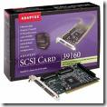
SCSI Controller Card I just installed a new hard drive, but now get intermittent lock ups on boot, error messages that I cannot read from the hard drive, or errors that show problems with the hard drive or file system. What should I explore first?

Note: This document applies to Mac OS 8.6 thru 9.x.

Some operating systems do not support all default SCSI drive features. If you are using a generic (not MAC branded) hard drive, the drive may behave erratically as it may not be optimized for the operating system. If you are seeing these symptoms, find out if SCSI Mode Page editing is supported by the SCSI controller. Disable Initiate Synchronous Negotiation and Disconnect/Reconnect if available at the SCSI controller. Also Unit Attention. Run the Media Verify option from the SCSI controller utilities, to verify data integrity on the hard drive.

These features may not be available at all SCSI controllers. Third party software may be needed to set the hard drive SCSI Mode pages for these features. You will need a SCSI Mode Page Editor tool. See your system manufacturer for SCSI tools.

Isolate the suspect drive to the only device on the controller and retest. Replace the data cable, devices, or external terminators. Verify that both ends of the SCSI bus are terminated. If the hard drive has an option for Termination Power–use it. Or confirm that the SCSI controller supports/supplies bus Termination Power. This is especially important with long cable runs or when using more than one SCSI device.

Read More

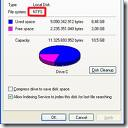
Limitations of FAT32 File System

FAT32 File System The following limitations exist using the FAT32 file system with Windows operating systems:

  • Clusters cannot be 64 kilobytes (KB) or larger. If clusters were 64 KB or larger, some programs (such as Setup programs) might calculate disk space incorrectly.
  • A volume must contain at least 65,527 clusters to use the FAT32 file system. You cannot increase the cluster size on a volume using the FAT32 file system so that it ends up with less than 65,527 clusters.
  • The maximum possible number of clusters on a volume using the FAT32 file system is 268,435,445. With a maximum of 32 KB per cluster with space for the file allocation table (FAT), this equates to a maximum disk size of approximately 8 terabytes (TB).
  • The ScanDisk tool included with Microsoft Windows 95 and Microsoft Windows 98 is a 16-bit program. Such programs have a single memory block maximum allocation size of 16 MB less 64 KB. Therefore, The Windows 95 or Windows 98 ScanDisk tool cannot process volumes using the FAT32 file system that have a FAT larger than 16 MB less 64 KB in size. A FAT entry on a volume using the FAT32 file system uses 4 bytes, so ScanDisk cannot process the FAT on a volume using the FAT32 file system that defines more than 4,177,920 clusters (including the two reserved clusters). Including the FATs themselves, this works out, at the maximum of 32 KB per cluster, to a volume size of 127.53 gigabytes (GB).
  • You cannot decrease the cluster size on a volume using the FAT32 file system so that the FAT ends up larger than 16 MB less 64 KB in size.
  • You cannot format a volume larger than 32 GB in size using the FAT32 file system in Windows 2000. The Windows 2000 FastFAT driver can mount and support volumes larger than 32 GB that use the FAT32 file system (subject to the other limits), but you cannot create one using the Format tool. This behavior is by design. If you need to create a volume larger than 32 GB, use the NTFS file system instead.

NOTE: When attempting to format a FAT32 partition larger than 32 GB, the format fails near the end of the process with the following error:

Logical Disk Manager: Volume size too big.

FAT32 offers the best compatibility for PC and Mac operating systems, including cross-platform compatibility with the MAC OS X. However, FAT32 has inherent limitations in regards to file size, partition size, and performance.

Limitations under Windows, Mac OS 9, and Mac X:

  • A file cannot be transferred to a FAT32 partition if the file is larger than 4GB.
  • Apple’s Time Machine backup utility will not store data on FAT32 partitions.

Limitations under Windows 2000/XP/Vista:

  • A FAT32 partition cannot be created that is larger than 32GB.
  • A file cannot be transferred to a FAT32 partition if the file is larger than 4GB.
  • FAT32 file system performs more slowly than NTFS (Windows) or Mac OS Extended (HFS Plus, Mac).
Read More

‘Disk Full’ Error When using Microsoft Backup

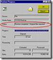
Microsoft Backup “Cannot copy filename. There is not enough free disk space.” or
“You have either run out of space, or the backup (.bkf) is too large for this disk. Note: If this is a disk formatted with FAT32, the maximum possible file size for the backup file is limited to 4GB.”

This error occurs due to a file system limitation within Microsoft. The file limitations are as follows:

Windows FAT 32 has a 4 GB limit.
Windows NTFS has a 2 TB (terabyte) limit using a Basic Partition. (Dynamic Volumes can be up to 16TB).

1394 and USB Personal Storage drives are pre-formatted in FAT 32. If the backup file is larger than 4 GB a file size error will occur. This is a Microsoft design and limitation. To backup or copy a file larger than 4 GB you must format the Personal Storage drive to NTFS. NTFS format only applies to Windows 2000 and XP. Use Disk Management in Windows 2000 and XP to format the drive. Windows 98 and Me users are limited to the FAT 32 file format and cannot format the drive to NTFS.

How to format the drive in NTFS under Windows 2000 and XP?

Note: This procedure is data destructive. Backup the data before performing this procedure.

  1. Access “Administrative Tools” through the “Control Panel”. XP user might have to click on “Performance and Maintenance” first to access “Administrative Tools”.
  2. In “Administrative Tools” click on “Computer Management”, “Storage”, and “Disk Management”.
  3. Right-click on the Drive Letter assigned to the Personal Storage device.
  4. Select “Delete Partition…” and “Yes”
  5. Right-click on the “Unallocated” space.
  6. Select “New Partition”.
  7. In the “New Partition Wizard”, click Next. Select the type of partition you want and follow all on-screen instructions.
Read More

Locating & Correcting Disk Space Problems on NTFS Volumes in Windows 2000/XP/Vista

NTFS Volumes Problem:
At times, Windows 2000, XP, and Vista misreport the amount of Free Disk Space on a hard drive – whether it is an internal drive or external drive.

Cause:
There are several causes for this:

  • The cluster size of the NTFS volume is too large for the average-sized files that are being stored.
  • File attributes or NTFS permissions prevent files or folders from being either displayed or accessed when you use either Microsoft Windows Explorer or a Windows command prompt.
  • The folder path exceed 255 characters.
  • Folders or files contain invalid or reserved file names.
  • NTFS metafiles (such as the Master File Table [MFT]) have grown and cannot be unallocated.
  • Files or folders contain alternate data streams.
  • NTFS corruption causes Windows to report free space as being in use.
  • Other NTFS features cause file-allocation confusion.

Solution:
Microsoft provides various solutions for symptom identified. Reference Microsoft Knowledge Base Articles 315688 (for Windows XP) and 303079 (for Windows 2000) for more information.

Read More