IDE/EIDE Interface Part I

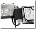
IDE/EIDE Interface This is a general description of the most frequently asked questions about the IDE/EIDE Interface. This information is meant only to address basic troubleshooting of IDE/EIDE compatibility issues, and is not meant to be an in-depth discussion of all possible error issues. Our purpose is to aid you in solving basic IDE/EIDE difficulties that may arise.

Issues Covered:

  • IDE/EIDE Definitions
  • Compatibility Issues

1. What is IDE/ATA?
Integrated Drive Electronics (IDE) is a generic term applied to any drive with an integrated (built-in) disk controller. The first drives with integrated controller were Hardcards. In the IDE architecture, the disk controller is integrated into the drive. This combination drive/controller assembly usually plugs into an interface on the motherboard or an interface card plugged into an empty bus slot. The ATA Specification is simply a set of rules or guidelines that an IDE drive should conform to.

2. What does the IDE interface actually do?
The primary job of the IDE interface is to transmit/receive data to and from the drive.

3. Why place the Controller on the drive itself?
Placing the controller on the drive gives IDE drives built-in reliability because data encoding, from digital to analog is performed directly on the drive in a tight, noise-free environment. The timing-sensitive analog information does not have to travel along ribbon cables that may pick up noise and insert propagation delays into the signals. The integrated configuration allows for increases in the clock rate of the encoder, as well as the storage density of drive.

4. What is Enhanced-IDE (EIDE) and Fast-ATA?

Enhanced IDE (EIDE) was a marketing program first initiated by Western Digital. EIDE has two sides:

  • Software – the Enhanced BIOS Specification that surpasses the 504 MB hard drive capacity limitation
  • Hardware – hard drives that conform to the ATA-2 and ATA-PI Standards

Fast-ATA, EIDE’s counterpart, was a separate marketing program that was introduced by Seagate and Quantum. This program leaned conservatively toward the ATA-2 specification.

5. What are the main features of EIDE

These are the main features:

  • Faster transfer modes- PIO modes 3-4, DMA mode 2 and UDMA.
  • Multiple Read/Write commands
  • LBA mode, translation for drives larger than 504 MB
  • Four devices on the ATA controller (secondary port)
  • CD ROM and Tape Drive support

6. Is ATA-5, 6 or 7 compatible with older IDE drives?

Older IDE peripherals will work with newer enhanced drives. However you will not be able to fully utilize the enhanced features of your ATA-5, 6 or 7 peripherals.

7. Is ATA-5, 6 or 7 compatible with older IDE controller cards?

EIDE drives are backward compatible with non-EIDE (standard) controller cards. However, an EIDE card will only perform at the capabilities of the controller; hence the EIDE drive will perform like a standard IDE drive.

8. What is ATA-PI

AT Attachment Packet Interface (ATA-PI) is a standard that implements SCSI like devices on the ATA bus. Devices like CD-ROM’s, tape drives and other removable media. The advantages of ATAPI are:

  • It is inexpensive
  • It is easy to implement in current systems.

ATAPI’s disadvantage is that it requires the use of software drivers for operability.

9. What is Cable Select (CSEL)?

Cable Select (CSEL) is an optional feature per the ANSI ATA specification. It is an alternative method of identifying the difference between device 0 and device 1 on an IDE interface cable. Hard drives configured in a multiple drive system are identified by CSEL’s value:

  • If CSEL is grounded, then the drive address is 0.
  • If CSEL is open, then the drive address is 1.

Additionally, CSEL requires a specialized (and more expensive) 40-pin 80-wire IDE interface cable, unlike the standard EIDE interface cable that is far more commonly used. We do not recommend using the CABLE SELECT feature unless your specific computer system documentation requires its use.

10. How does my computer know which drive is the Master and which is the Slave?

When only one drive is installed, the single drives controller responds to all commands from the system. When two drives (which means two drive controllers) are installed, both controllers receive all commands from the system. Each drives controller must then be configured to respond only to commands issued to it. In this situation, one controller must be designated as master and the other as slave. When the system sends a command to a specific drive, the other drive’s controller must remain silent. A special bit (the DRV bit) is used in the Drive/Head Register to distinguish between the controllers.

Read More

IDE/EIDE Interface Part II

IDE/EIDE Interface This is a general description of the most frequently asked questions about the IDE/EIDE Interface. This information is meant only to address basic troubleshooting of IDE/EIDE compatibility issues, and is not meant to be an in-depth discussion of all possible error issues. Our purpose is to aid you in solving basic IDE/EIDE difficulties that may arise.

Issues Covered:

  • IDE/EIDE Definitions
  • Compatibility Issues

11.Why is the 20th hole plugged on the Ribbon Connector?

It is a means of preventing the cable from being installed (plugged in) upside down. Users that inadvertently plug a cable in backwards can cause damage to both the hard drive and the motherboards interface. If your system does not have the corresponding missing pin, you may remove this plug by “teasing it out” with a straight pin.

12. Does the IDE interface cable influence data integrity, signal noise issues and drive recognition?

The answer is Yes! The ATA standard specifies that an IDE Interface cable should be no longer than 18 inches. The standard cable used today conforms to the ATA specifications. However, 40 pin interface cables do not always filter out noise when used with the Ultra DMA 33, 66, 100 and even 133 hard drives of today. Another option for reduction of cable noise would be to use an 40-pin 80-wire interface cable. These cables provide better grounding to maximize signal integrity.

13. Will adding an EIDE Interface increase disk performance?

Although most, if not all computers manufactured today have the fastest interface available, the answer really depends on the hard disk drive. Unless you’re working with legacy equipment, a new interface may not give you a performance increase. As an example, upgrading an ISA controller to a PCI controller would be the biggest improvement a user could make.

14. Why is the hard disk drive NOT as fast as advertised?

Advertised transfer rates are based on the fastest speed at which the drive can send data across the ribbon cable from the drive buffer, with the transfer stopping temporarily every time the buffer re-fills. This process continues until a command is complete. Data transfer rates will differ between system configurations, as a drive is not the single component that decides transfer rates. The one thing that designers have control of is the speed at which data transmits across the data ribbon cable from the drive’s buffer, but not how your other components interact with the drive.

15. Why is it that an old IDE drive may not work with a New IDE drive?

The reason is the fact that many hard drive manufacturers were already making and selling drives before the IDE standard was clearly defined. While this is now, for the most part, relegated to very old IDE drives that have problems functioning in dual-drive configurations. This scenario was more prevalent when the hard disk drives are from different manufacturers, however, in some cases, two drives may not function together at all. Even today though, in rare circumstances even new drives will not work together.

16. Why is my new IDE drive not recognized as a slave or a master?

Configuring IDE drives can be simple, as is the case with most single-drive installations, or troublesome, especially when mixing drives from different manufacturers on a single cable. Most IDE drives must be configured in one of the following ways:

  1. Single-drive (master)
  2. Master in a dual-drive system
  3. Slave in a dual-drive system

Because each IDE drive has its own controller, one drive must be jumped as a master and the other as the slave. There are no functional differences between the two, except that the drive that’s specified as the slave will assert the DASP (Drive Active/Slave Present) signal after a system reset to inform the master that a slave drive is present in the system. Daisy-chained hard disk drives that do not have their jumpers set correctly will not function. You should contact the disk drive manufacturer if you are unsure of proper jumper settings.

17. Two hard disk drives will not function even after verifying jumper settings. What could be wrong?

There may be a compatibility problem between the two drives. Use the following steps to verify the function of each drive:

  1. Test each drive by itself, making sure that each drive has been jumpered correctly. If both drives work by themselves, you may conclude that there is a compatibility problem.
  2. Try “swapping” (switching) the drive’s position, what was the master will be changed to a slave and the slave will become the master.
  3. Most motherboards have two IDE bus connectors. Place one drive on each IDE bus and test the system.

18. Why does an IDE CD-ROM and Tape Backup not work when attached to the Interface?

On  occasion, attaching an IDE CD-ROM or tape backup drive to a bus that supports an IDE drive, can slow down and even compromise the drive’s data integrity. Although this is extremely rare today, make sure that your systems motherboard has an Enhanced IDE interface that is ATAPI compliant. If it is not, you can purchase and add-in card that has this interface, and they usually come with a secondary IDE interface built on the same card.

19. Even after switching roles, my hard drives still will not work. What else can I do?

First, see questions 16 and 17 above. We recommend that you separate the hard drives and connect them to the different interface ports (IDE buses) of the system. If the system does NOT have a Secondary IDE interface, we recommend that you install an EIDE interface card. By doing so, each of your drives would be able to communicate individually with the system. Enhanced EIDE cards also can add BIOS LBA support and enhanced performance for the drives.

20. Why are 80-wire, 40-pin ribbon cables required for certain hard drive configurations?

40-conductor cables support only up to 33MB/sec transfers (and should only be used for up to 16MB/sec or less in our opinion), while 80-conductor cables support up to 100MB/sec. Thus you can always replace a 40-conductor cable with an 80-conductor cable, but not the other way around without seriously hurting transfer speeds, and quite possibly damaging one or more of your systems components.

Read More

Hard Drive Crash

Hard Drive Crash Sometimes a hard drive may experience failure or sudden crash without any warning, but many times there are warning signs that will let you know when to take action. Changes in performance, intermittent failures, or unexpected blue screens are major signs that the hard drive may be dying out permanently. The most obvious warning sign with a hard drive is unusual clicking, grinding, or scraping noises.

In practice, the term hard drive crash often refers to both mechanical or electrical failue and logical failure. The case of mechanical / electrical hard drive crash is the worst, it requires professional help of data recovery service, recovery programs won’t help.

Hard Drive Crash Signs

If your PC is experiencing any of the following signs of impeding doom then you must run (not walk) and grab CDs to burn backups of all your essential data.

Sign 1 – You hear high-pitched whining, loud clicking or grinding noises coming from the drive
A normally operating drive will make a smooth “whirling” sound as is spins up or down. But if a drive has a grinding or clicking sounds (the Read/Write heads scraping too close to the magnetic platters), then your drive is sick and is on the way out.

Sign 2 – You see the infamous “Blue Screen of Death“, repeatedly
BSODs (Blue Screens of Death) are actually called “Stop” errors and they only appear when your Windows system is experiencing severe software or hardware issues. Often BSODs can cured with a careful “Repair Install” of the Windows operating system or by removal of a bad device driver. But if these software fast fixes don’t seem stick, then your hard drive is usually on its last legs

Sign 3 – Your computer keeps re-booting on its own
I admit, I have only seen this problem a few times in my 18+ year career and in all instances it was due to hardware issues. Once it was a dust covered motherboard, and another time an overheating processor. But all the other times it was due to bad drives.

Sign 4 – Your system keeps having frequent freezes or hang ups
You are working along just fine, and then suddenly everything comes to a halt. The program freezes up on you. Your mouse and keyboard seem to stop responding. The only solution is to reboot.

Sign 5 – Error message: hard drive is not formatted
This a fun message that you will get when you start up your machine. You maybe able to restart and get it to boot into Windows a few more times but this error is “fur-sure” sign that you drive is very close to death. And by the way don’t try to format the drive! You will lose all your data.

Sign 6 – Error message: boot drive or device not found or drive cannot be accessed
This is another favorite of mine. You can check the CD/DVD trays or the floppy drive to make sure no stray disks are stuck inside. You can also check the BIOS to make sure the system is booting from the hard drive first. If all these tests are no-good, then the drive is a goner.

Sign 7 – Errors: Operating system not found or Missing Operating System
This is a bad one. Even the Microsoft technical support knowledgebase has only got a few causes for this error message. Basically your PC can no longer detect the hard drive or the drive is too severely damaged to read (DOA).

What to do if your drive has any of these signs?

1) First, listen up, if possible, BACKUP YOUR FILES NOW!
2) Create a boot disk and run Windows Scandisk and set it to automatically fix errors. If it finds more than a few bad sectors then see the point above
3) If possible download and use a hard drive diagnostic program. All the major hard drive manufacturers have free utilities on their websites.

WARNING:

You should never open the cover of a failed hard disk drive in attempt to repair, salvage or recover data. Today’s hard disk drives tolerances are very tight and the materials used inside are so technologically advanced that even the smallest speck of dust, contaminants or even gaseous can disrupt the delicate balance of the drives ecosystem. Any such disruption not only destroys the drive but all the data contained on it.

Read More

Sustained Data Transfer Rates For SCSI Hard Drive

Data Transfer Rate Many factors contribute to disk drive performance. One useful measure is data throughput rate or sustained transfer rate. In general, higher data transfer rates from the disk to the computer lead to improved system performance. Data transfer rates are often quoted within the “Specifications” section of the product manuals. Yet it is important to realize that controller overhead, cable quality and termination issues (on older SCSI products) are major factors that affect sustained data transfer rates.

The following specifications are from an older SCSI hard drive. These numbers are used for example, but the same calculations apply to ATA drives. Notice that the internal data transfer rate is listed as sustained, while the external data transfer rate is listed as burst.

INTERNAL DATA TRANSFER RATE (Megabits/sec.)____194 to 340 (sustained)

EXTERNAL DATA TRANSFER RATE – Buffer to SCSI controller (Megabytes/Sec)___Ultra160/m 160 MB/Sec. (burst)

As there are 8 bits to a byte, and 8 Megabits (Mb) to a Megabyte (MB), we divide 194 Mb’s/sec. by 8 to get 24.25 Megabytes/sec. The drive should sustain a transfer rate of 24.25 MB/sec. from the drive platters to the read/write heads, even under the worst possible conditions. The lower number of the range measures data transfer from the inner diameter of the drive platters, where there are the least amount of sectors per track. The higher number of the range measures data transfer from the outer diameter of the drive platters, where the number of sectors is higher per track. Using the higher number of the range (340), the result is 42.5 MB/Sec.

We then have a data rate in Megabytes, of 24.25 to 42.5 MB/sec. Since this is an ‘internal’ data transfer rate, consider it as the raw data rate. Some of this internal rate is lost when translating to the user data rate, because this raw data includes coding overhead that adds length to the user’s data. Add a 25% allowance (more for some drives) for system overhead. In the case of this older SCSI drive, the overhead is approximately 30%. The sustained (user) data rates are actually listed at 17 to 29 MB/Sec. For drives where only the internal data rate is listed, the formula ([Internal rate in Mb/8] x .75 = Approx. data rate in MB ) is used to develop an approximate user data rate.

Most of the time you won’t be getting the lowest sustained transfer performance or the highest, so we should find an average. Using the average of the sustained transfer rates ([17+29]/2=23), you receive an expected average sustained data transfer rate of 23 Mbytes/sec.

It’s very important to realize how these numbers are presented. The internal data rate shown here is expressed in Megabits/sec, the user data rate is written in Megabytes/sec. Certainly, we can tell you, assuming your SCSI (or ATA) subsystem is configured correctly, what your expected sustained transfer rates should be. In this case, a sustained transfer rate of 17 MBytes/sec. to 29MBytes/sec. is acceptable. Your transfer rates may be higher–or lower.

If your sustained user data rates are lower than expected, this indicates a bottleneck in the system. A failing device, improper configuration, and termination issues are leading causes for poor performance. Be aware that transfer rates can be reduced by several issues–poor quality cables, improper cable routing (causes signal reflection), SCSI Single Ended devices on an LVD SCSI bus, host limitations and more.

While you might expect to see 320 MB/sec. transfer from your SCSI Ultra 320 devices, or 300 MB/sec. from a SATA drive, know that these specifications are the burst rate–what the drive’s cache memory buffer can process under the absolute perfect combination of drive, cable, and hard drive controller conditions. Even ambient temperature affects transfer rates. This is not the sustained transfer rate of the drive. It’s what the input/output subsystem is capable of handling. For hard drives, sustained transfer rates are an important benchmark. Only when combining several high-speed drives together (in a performance RAID array), does one approach ‘bus saturation’ speeds.

Read More

Free Partition Manager: Gnome Partition Editor

Free Partition Manager - Gnome Partition Editor File Name: Gnome Partition Editor
Version: 0.4.5-2
Publisher: Bart Hakvoort (plors)
Languages:
English
OS: GNU/Linux/Windows
Price: Free

The GParted application is the GNOME partition editor for creating partitions, reorganizing partitions, and deleting disk partitions.

A disk device can be subdivided into one or more partitions. The GParted application enables you to change the partition organization on a disk device while preserving the contents of the partitions.

Main Features

With GParted you can accomplish the following tasks:

  • Create a partition table on a disk device.
  • Enable and disable partition flags such as boot and hidden.
  • Perform actions with partitions such as:
    • create partition or delete partition
    • resize partition or move partition
    • check
    • label
    • copy and paste

    GParted is developed on GNU/Linux. It can be used on other operating systems, such as Windows, by booting from media containing GParted Live.

    GParted is free and open source software available under the terms of the GNU General Public License.

    Related Links:

  • Gnome Partition Editor Screenshots
  • Gnome Partition Editor Free Download

Note:

Editing partitions has the potential to cause LOSS of DATA.
You are advised to BACKUP your DATA before using the gparted application.

Read More

Seagate Firmware Update Utility Step by Step

This is a help post for seagate windows firmware update utility which may be downloaded from seagate firmware update pages.

Your drive is eligible for a firmware update?

Seagate Firmware Update Utility Seagate products are run by firmware.  Having the latest firmware can improve performance and or reliability of your product.  Seagate recommends applying new firmware to enhance the performance and or reliability of your drive.

Like any software, firmware is improved over time and problems are also fixed.  Every drive family has a couple of firmware releases during the life of the product.  Please check in regularly to determine if new firmware is available for your drive.

If newer firmware is available for your drive, it will reflect the improvements we have engineered for the latest manufacturing.  Firmware for legacy products will be the final release from manufacturing.  Please note that Seagate does not offer details about specific firmware.

Until recently, firmware updates for typical desktop and laptop computers were difficult and somewhat risky.  This situation, in part, was based on a lack of friendly firmware download tools and operating system limitations.  This situation has improved and Seagate now offers firmware updates as a routine matter for the general support of your Seagate drive.

Note: If you are troubleshooting a system or OS problem, you should not consider firmware updates until after exploring more typical troubleshooting steps like file system error checking and anti-virus scanning.

Firmware update step by step

1) Choose from the list of languages.  The screens in Windows will be translated to your selection.  When the application restarts in DOS, the language will be in English.

Firmware Update Tool
(Click to expand.)

2) Welcome screen.
Be sure inspect the title, which gives a description of what products and firmware versions are supported by this package.  This screen contains an important warning to remind you to back up your system.

Firmware Update Tool
(Click to expand.)

3) End User License Agreement

Firmware Update Tool
(Click to expand.)

4) Very important instructions and warnings.  Again, they are:

DO NOT run this firmware update on RAID systems.
DO NOT turn the power off during the firmware update procedure.

BEFORE YOU BEGIN:

  1. Make sure you have backed up all of your important files and critical data to some other storage media.
  2. Save any work in progress.
  3. Close all other open applications.
  4. Disconnect all external storage devices.

Windows will shut down and your system will reboot.  You will see a new boot message “Starting Seagate Loader…” and “Starting Seagate Firmware Update Utility…”
Do not interrupt this procedure.

Firmware Update Tool
(Click to expand.)

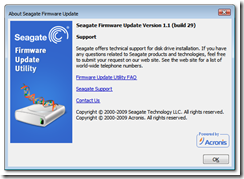
5) About screen

Firmware Update Tool
(Click to expand.)

6) Windows will shut down and the system will reboot.

Firmware Update Tool
(Click to expand.)

7) These are the first screens you will see after the reboot.
DO NOT INTERRUPT this procedure!

Firmware Update Tool Firmware Update Tool
(Click to expand.)

8) The SeaEnum utility will scan your system for hard disk drives and display the Model Number, Serial Number and current Firmware Revision for each drive.

Firmware Update Tool
(Click to expand.)

Try the Seagate Drive Detect utility if you want to see this information while in Windows.

9) The Firmware Update Utility runs from DOS to load the new firmware on your disk drive. This utility will upgrade the firmware on your Seagate disk drive if the drive model and the current firmware are compatible with this update.

This process may take a few minutes.  Afterwards, the utility will exit and reboot.  If the software is unable to automatically reboot system, you may restart the system yourself.

Firmware Update Tool
(Click to expand.)

Besides the “Sending data” firmware download message, other common messages are:

  • Firmware Already Updated! Will not download firmware. – The current version on the disk drive matches the version supplied in this update.
  • Model Matched, No Firmware Matched!  Will not download firmware. – Even though the model is a match, the current version on the disk is not compatible with the version supplied in this update.
  • No Model Matched! Will not download firmware.
  • Wrong Model, or Not a Seagate drive.

If the software determines that the update should not be run, the utility will exit and reboot back to Windows.

10) Windows starting to load.

Firmware Update Tool Firmware Update Tool
(Click to expand.)

Finished!

Related Link: Firmware Download Base

Read More

Free Partition Manager: EASEUS Partition Master Home Edition

EASEUS Partition Master Home Edition File Name: Partition Master
Version: Home Edition
Publisher: CHENGDU YIWO Tech Development Co., Ltd
Languages: English
OS: Windows 2000/XP/Vista (32 bit) operating system
Price: Free

EASEUS Partition Master Home Edition is a FREE disk partitioning utility for extending system partition, better disk space management, settling low disk space problem under Windows 2000/XP/Vista.

This free partition manager works perfectly with hardware RAID and laptops like HP, Dell, etc. Your data is completely protected during all operations.

If your computer is running 64 bit Windows systems, please check Professional or Server editions.

Main Features

  • Resize/Move partitions without data loss
  • Extend system partition easily and safely
  • Create partitions, Delete partitions and Format partitions with simple steps
  • Support up to 2TB partition or hard drive
  • Disk Copy, Partition Copy, Dynamic Disk Copy to protect or transfer data

Related Links

  • EASEUS Partition Master Screenshots
  • EASEUS Partition Master Home Edition Free Download
Read More

Free Partition Manager: Partition Wizard Home Edition

Free Partition Manager - Partition Wizard File Name: Partition Wizard
Version: Home Edition
Publisher: MT Solution Ltd
Languages: English
OS: Windows 2000/XP/Vista/Windows7 (32 bit & 64 bit) operating system
Price: Free

Partition Wizard Home Edition
is a free partition manager designed by MT Solution Ltd.  Home users can perform complicated partition operations by using this powerful but free partition manager to manage their hard disk partition such as Resizing partitions, Copying partitions, Create partition, Delete partition, Format partition, Convert partition, Explore partition, Hide partition, Change drive letter, Set active partition and Partition Recovery.

Partition Wizard Home Edition is designated for home user only, to use Partition Wizard in a business envirnoment, Partition Wizard Business Edition is required.

Main Features

  • Support RAID.
  • Extend system partition to improve computer performance to maximum.
  • Manage the hard disk to get the best performance of computer.
  • Create Partitions , Delete Partitions and Format partitions with simple steps.
  • Disk Copy to protect or transfer data.
  • Support disk and partition size larger than 2TB.
  • Convert partition format from FAT to NTFS.
  • Partition Copy: Copy the entire hard disk to another one.
  • Copy Disk Wizard: Copy the entire hard disk to another one without windows reinstalling.
  • Disk Map – Visually demonstrate your disk/partition configuration; preview the changes before applying.
  • Hide/unhide partition, set active partition, etc. – Change partition properties.
  • Explore FAT/NTFS partition.Related Links:
  • Partition Wizard Sceenshots
  • Partition Wizard Download
Read More

Install and Troubleshoot Serial ATA (SATA) Hard Drives in a Macintosh

Sata Hard Drive Serial ATA interface disk drives are designed for easy installation. It is not necessary to set any jumpers, terminators, or other settings on this drive for proper operation. The jumper block adjacent to the SATA interface connector on SATA 150MB/s drives is for factory use only.  The jumper block adjacent to the SATA interface connector on SATA 300MB/s drives can be used to force the drive into SATA 150MB/s mode for use with older SATA controllers that only work with SATA 150MB/s drives.

With a Serial ATA interface, each disk drive has its own cable that connects directly to a Serial ATA host adapter or a Serial ATA port on your motherboard. Unlike Parallel ATA, there is no master-slave relationship between drives that use a Serial ATA interface.

You can use a Serial ATA drive in the same system with Parallel ATA drives as long as both interfaces are supported on the motherboard or with a host adapter. This makes it easy to add Serial ATA compatibility to your existing system without removing existing Parallel ATA disk drives.

What You Need?

  • A Phillips screwdriver and four 6-32 UNC drive mounting screws.
  • A Serial ATA interface cable (sold separately). Maximum length is 39 inches (1 meter).
  • A Serial ATA-compatible power cable or adapter (sold separately).
  • A system with a motherboard that has a Serial ATA connector on it, or a Serial ATA host adapter and available PCI slot in which to install the adapter.

Refer to your computer system documentation to see if your system supports Serial ATA on the motherboard and to locate the Serial ATA connector. If your system does not have a Serial ATA connector on the motherboard, you must purchase a Serial ATA host adapter that is compatible with your computer and operating system and install it with the appropriate device driver according to the host adapter manufacturer’s installation instructions.

Handling Precautions

  • Disc drives are fragile. Do not drop or jar the drive. Handle the drive only by the edges or frame. Keep the drive in the protective anti-static container until you are ready to install it to minimize handling damage.
  • Drive electronics are extremely sensitive to static electricity. While installing the drive, wear a wrist strap and cable connected to ground.
  • Turn off the power to the host system during installation.
  • Do not disassemble the drive. Doing so voids the warranty.
  • Do not apply pressure or attach labels to the circuit board or to the top of the drive.

See your Power Mac or Macintosh Server documentation for information about internal storage options and installation instructions.

Note: You must purchase and install a Mac OS-compatible Serial ATA host adapter into an open PCI slot to install this drive in your Macintosh.

Mounting the Drive

  1. Turn off your computer.
  2. Open your computer case (See your computer manual for instructions).
  3. Slide your new drive into an open drive bay.
    Orient the drive with the drive label facing up and the PCB facing down. You may find it easier to attach cables to your new drive before installing it. If so, follow the cabling steps below, and then return to this step to install the drive.
  4. Use four (4) mounting screws to secure your drive.
    If you want to mount your new Seagate drive in a 5.25-inch drive bay, you must purchase drive rails at a computer supply store.

Attaching the Cables

  1. Attach the cables to your new drive.
    Attach the Serial ATA interface and power-adapter cables. Connect either end of the interface cable to the drive. Both connectors are keyed the same to ensure proper orientation. You can connect only one end of the power-adapter cable to the drive. That connector is also keyed to ensure proper orientation.
    Note: Do not disturb the power and interface cables that are attached to your existing drive.
  2. Attach the Serial ATA interface cable to your computer.
    Connect the open end of your Serial ATA interface cable directly to your motherboard if your computer supports Serial ATA. If not, you must have an open PCI slot on your motherboard into which you install a Serial ATA host adapter (sold separately).
  3. Connect your power-adapter cable
    Connect the open end of the Serial ATA power-adapter cable to any available connector from your computer’s power supply. If none is available, you can purchase a Y-adapter cable to convert any one existing power connector into two, one of which you can use to power your new drive.

Initialize Your Drive

Use one of the following Apple utilities to initialize your new drive:

Mac OS X
Use Apple’s Disk Utility application.

Mac OS 9
Use Apple’s Drive Setup application.

These applications are normally located in your Applications/Utilities folder.

Note: DiscWizard is a PC (Windows/DOS) application. You do not need DiscWizard to install your drive in a Macintosh system.

Troubleshooting

If your drive is not working properly, these troubleshooting tips may help solve the problem.

  1. Does the drive spin up?
    A spinning drive produces a faint whine and clicking noise. If your drive does not spin, check that the power connector and interface cable are securely attached.
  2. Does the computer recognize the drive?
    Verify that the drive is enabled in the system CMOS or setup program. If not, select the autodetect option and enable it. If your drive has a problem, it may not be recognized by the system. If the operating system does not recognize the drive, you need to load your host adapter drivers.
  3. Why does my computer hang on startup?
    Verify that your system is Serial ATA compatible. You need either a Serial ATA 1.0-compatible motherboard connector or Serial ATA host adapter to use this drive.
Read More

How to install, format, and partition internal PATA/SATA drive in Vista?

How to install Internal hard drive installation instructions for Windows Vista using Vista installation process or Disk Management.

It is recommended you use Windows Vista to format and partition your hard disk drive when installing Vista on a boot drive or adding a drive as additional storage.

DiscWizard is your best choice if you want your new drive to become the new boot drive.  To do that, the operating system and the files on the old boot drive need to be copied to the new drive.

The following are step-by-step installation instructions on how to format and partition a drive in Windows Vista.

Fresh Vista Install:

  1. Physically install the hard drive in your computer. If this is a PATA / IDE drive, set the BIOS to Auto-Detect the hard disk. If this is a SATA drive, on some systems you may need to enable the SATA port in the BIOS before the computer recognizes the drive. For further information on navigating your system’s BIOS, please consult with your computer manufacturer’s documentation.
  2. Insert the Windows Vista CD-ROM and restart the computer.
  3. Follow on-screen prompts for setup. When installing Vista fresh on this hard drive, at the screen titled, “Which type of installation do you want?”, click Custom (advanced).
  4. At the “Where do you want to install Windows?” screen, select Disk 0 Unallocated Space and click Next.
  5. If this is a SATA drive and it is not recognized in the above step, you may need to install drivers provided by the motherboard manufacturer if the drive is connected directly to the motherboard, or install drivers provided by the controller card manufacturer if the drive is connected directly to a SATA PCI controller card. To install the driver for the SATA controller on the motherboard or PCI controller card, you will need to click Load Driver.
    Note: there are no Vista drivers provided by Seagate for any Seagate or Maxtor branded PATA or SATA drive, as the drives themselves are all Plug-and-Play within Windows Vista when connected internally on your computer.
  6. From here, proceed with the rest of the Vista installation.

Installing an Additional Data Drive in Windows Vista:
Note:If the second drive is pre-formatted or used in another Windows system, it is not necessary to re-format the drive. Follow the instructions below up to Step 2 and Vista should recognize the drive.

  1. Physically install the hard drive in your computer. If this is a PATA / IDE drive, set the BIOS to Auto-Detect the hard disk. If this is a SATA drive, on some systems you may need to enable the SATA port in the BIOS before the computer recognizes the drive. For further information on navigating your system’s BIOS, please consult with your computer manufacturer’s documentation.
  2. Restart the computer and boot into Windows Vista.
  3. Click on the Start button and select Control Panel. In the Control Panel, click on System and Maintenance. Scroll down and click on Administrative Tools. Double-click on Computer Management. On the left-hand side of the Computer Management window, click on Disk Management, located in the Storage section.
  4. In Disk Management you will see the active hard disks. Be patient, as it may take a minute or two for it to load the disk information. On the bottom half, you will see Disk 0, which is the Primary (or C:) drive. Disk 1 and greater are generally considered secondary storage drives.
  5. If the description of Disk 1 is “Not Initialized” then you must right-click on the Disk 1 icon and select Initialize.
  6. In the window that appears, click on the disk to be initialized and click on OK.
  7. Next, right-click on the Unallocated region of the basic disk, and select New Simple Volume.
  8. In the New Partition Wizard, click Next. Select the type of partition you want and follow all on-screen instructions.  After finishing, the section of the disk that said “Unallocated” should say “Formatting” for a few seconds.  Once it is finished formatting, it will say, “Healthy”.
Read More