IBM malfunctions

Manufacturer: IBM, drive families: DJNA, DPTA, DTLA, AVER, AVVA
Malfunction signs: A drive spins up the spindle motor, recalibrates itself, reports on readiness, BIOS identifies it correctly but at a reading attempt the drive produces “scratching” sounds and reveals numerous BAD sectors on its surfaces.

That malfunction is connected with a mismatch between the cyclical redundancy check code in the data fields and the information recorded in the sector service field. Such a situation appears when recording to a sector is unfinished. That may result from lack of contact at the connector between the PCB and HDA. That connector consists of needle-like pins touching tinned pads on the PCB (please see figure 11). With time soft solder becomes perforated and contact quality deteriorates.

Figure 11. Pin contacts of magnetic heads’ assembly connector in IBM drives (view from behind the PCB)

In order to repair that malfunction you should remove the control board, clean the old solder off the contact pads and cover them again using silver-based solder, then carefully wash the soldered location. Install the board back to HDA. Then you will have to clear the whole disk surface overwriting it with any code using freely available software (please see part 4); that will accomplish recording of correct CRC codes.

Read More

Fujitsu malfunctions

Fujitsu, M1638TAU drive family
Malfunction signs: The spindle motor does not start
The connection scheme of VCM (Voice Coil Motor) & SPM (Spindle Motor) controller is practically identical for the following drive families: M1614TAU, M1638TAU, MPA30xxAT, MPB30xxAT and MPC30xxAT.

VCM&SPM controller regulates 3-phase motor; it is programmed by the MB9004 processor produced by Fujitsu. There are three modes of spindle motor control: start mode, acceleration mode and stable rotation mode. In the start mode at power-up Power Monitor (MP3771) sends a “reset” signal to the microprocessor (MB9004) and the VCM & SPM controller. Microprocessor uses a serial channel to program internal registers of VCM & SPM controller for a start and charges the pump capacitor of the controller using the “Charge pump” signal. Charge volume determines the current which will flow to the spindle motor. As soon as the start-up capacitor is charged sufficiently the microprocessor programs SPM controller for a start mode, then ~ 1,3А current flows to the spindle motor. Controller generates phase switching signals. The spindle motor at that begins rotation generating self-induced EMF. The controller detects EMF and notifies the microprocessor about that; the latter uses the signal for rotation control. In the acceleration mode the microprocessor speeds up phase switching and measures spindle motor rotational speed until it reaches 5400 RPM. When the speed is reached the controller switches to stable rotation. In that mode microprocessor calculates the time required for one spindle motor revolution on the basis of the phase signal and adjusts the rotational speed charging or discharging the pump capacitor. Adjustment control (charge/discharge) is performed every 1/6 spindle revolution.

The complexity of diagnostics is determined by the fact that SPM controller monitors EMF generated during spindle rotation and at an attempt of spindle spin-up it makes just 2 – 3 phase switches which are difficult to track using oscilloscope. If the spindle does not begin rotation (for whatever reason) the controller, as a rule, either switches off or retries its attempt after some time. Thus, if you use a regular oscilloscope, you can see only presence of pulses falling within a certain range, which is insufficient for complete diagnostics. In an ideal case we would recommend using 3-channel oscilloscope with memory function operating in the automatic recorder mode. Probably such device is not really commonplace. Therefore it is possible just to check the presence of pulses for motor phases.

VCM & SPM controller is a quite reliable microchip and it rarely goes out of order. More frequently a spindle motor does not start because of other malfunctions. Still, if the chip fails such failure is usually caused by overheating with clearly visible traces on chip case. During repair of the start circuit you should check the Stop Spindle signal from the MB3771 chip. The signal forces parking of magnetic heads and stops the spindle motor with keys Q8 and Q9. Active level of that signal in the parking mode is “1”, in the operational drive mode it is “0”. If a spindle motor begins to spin up you can check the operation of output keys of HA13525A chip controlling phase signal with oscilloscope. To do so select 10 ms/div sweep with 2V/div amplification (it is advisable to use the 1:10 multiplier). A phase may be diverted by a disrupted Q8 or Q9 key. HA13525A and HA13525B chips are compatible from top downward, i.e. in models belonging to the M1638TAU and MPA drive families both of those chips can be used. In MPB and MPC drive families only HA13525B is allowed.

Manufacturer: Fujitsu, drive families: MPB, MPC
Malfunction signs: A drive begins to detect a higher own capacity than the actual rated value, the so-called “megalomania”.

That malfunction is quite frequent in the above-mentioned drive families; it is caused by corruption of firmware in Flash ROM chip on the control board of the drive. Those drive families employ Flash ROM chips using 64К structure based on 16-bit words, programming voltage is 5 or 12 V, package type is PLCC44.

Elimination of that malfunction requires just reprogramming of Flash chip by recording a known good firmware of the corresponding version. Version number in Fujitsu drives is indicated in the lower right corner of the label over HDA below bar code and it looks like: xyy-zzzz, where x –means the month when the drive was manufactured in hexadecimal notation, yy – means version prefix and zzzz – means the actual firmware version, e.g.: С02-2009. For version compatibility in MPB and MPC drive families just the actual version match is sufficient, the prefix and month of manufacture are not important.

Manufacturer: Fujitsu, MPG3xxxAT/AH drive family
Malfunction signs: Quite unexpectedly for user and user data a drive is no longer identified in PC BIOS.

We should note that this very drive model has broken all records of failures, which happen in most cases after a year of operation, just after completion of the warranty period. The main cause of the malfunction was in the Cirrus Logic CL-SH8671-450E chip. It can hardly be replaced with a working chip because those microcircuits were produced for a special Fujitsu order and the manufacture of that drive family was discontinued long ago. However, there is a method of “revival” and “revitalizing” a malfunctioning chip which allows extending HDD life a little. However, if you ignore drive “hangings” and do not take due steps (at least backup valuable data) the table of S.M.A.R.T. logs in firmware zone will be gradually overfilled and the drive will additionally corrupt its modules in firmware zone, which cannot be restored without specialized software.

One of the versions explaining the cause of problems with those chips is the use of a new polymer compound during production of chip case. The compound decomposes under the influence of increased temperature in humid conditions producing phosphoric acid. But it is just a version; we may never learn whether it is so or not. However, one thing is known for sure: if you unsolder that chip, remove old solder from its pins and contact pads on the board, flush the location for the chip and then solder it back the drive will begin to work properly.

Read More

Quantum malfunctions (Fireball drive families)

Manufacturer: Quantum, Quantum Fireball drive families: EL, EX, CR, CX, lct08, lct10, lct15

Malfunction signs: A drive operates normally for some time (from15 minutes to several hours), then it begins to hit its positioner against the limiting stop.

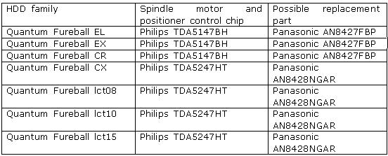
It is a very frequent malfunction in those drive families, it is caused by the chip controlling the spindle motor and positioner; the chip has poor quality of factory soldering (please see the table), overheats because of that and stops to function normally.

One peculiarity of the TDA5247HT (AN8428NGAR) microchip is the availability of space for soldering in the lower part of its case acting, by the way, as its heatsink. It accomplishes heat abstraction from the chip and its dissipation along the board. Thus mounting and removal of that chip should be performed using a thermal air unit.

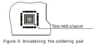
To repair that malfunction, you should unsolder the chip, broaden the soldering pad as shown in the figure 9 (that work can be performed using a lancet for removal of a portion of protective layer), blanch it and the lower part of the chip and solder the latter back pressing its case gently during soldering in such a manner that solder shows through board openings on the other side. Then you should carefully flush the soldered location because that chip has high-resistance analog outputs and fusing agent residue may disturb its normal operation.

That method undoubtedly improves the thermal conditions of the chip but it does not yield positive results always. If a chip used to be overheated for a long time, its resoldering does not remedy the situation. In that case the chip should be replaced. It is advisable to replace it with an identical model offered by Panasonic and having better thermal characteristics. Such chips can be purchased at stores selling electronic components. Its price may vary from 5 to 10$.

Read More

Some typical malfunctions of hard drives and methods of their repair

Always to make repairing hard drive it is necessary to use special complicated eqipments, but sometimes you need desoldering station and programmator only. In the last part of our descriptive survey we would like to address some typical malfunctions of hard drives and methods of their repair.

 As we have mentioned in our previous articles devoted to problems with hard disk drives, a drive consists of 2 main parts: a mechanical part (heads-and-disk assembly) and electronics (control printed circuit board). Those two components are supplemented with internal firmware, which is partially stored in ROM on PCB and partially resides within firmware zone of a drive (that latter portion is loaded to RAM of HDD microcontroller during its initialization). Those three components interact very closely and normal HDD operation is possible only when all of them function properly. Consequently a drive malfunction may result with equal probability from failure of any of the mentioned components, and that can be observed in real life. Moreover, in various HDD models from different manufacturers the frequency and degree of damage to different components is not the same. When a HDD has to be repaired in conditions offered by a regular (not specialized) laboratory we have to decline some repair orders. In the first place, it pertains to the repair of HDD mechanics – HDA, secondly – to the service data in the firmware area of a drive.

 The difficulty of HDA repair is connected, first of all, with exceptional purity of air contained under normal pressure inside the case (no more than 100 dust particles per 1 cubic meter of air). Opening a case in usual premises or in common laboratory conditions will inevitably lead to dust penetration inside (in usual rooms 1 cubic meter of air contains approximately 600 dust particles) and that is sure to cause damage to precise mechanics. Few companies, which perform repair of drive mechanics use in their work special clean rooms or clean worktables (tables equipped with a special “aquarium” with sleeves inside for performance of necessary work). Besides, a whole set of specialized tools is required including T type screwdrivers (from T9 to T3), hex screwdrivers, mounting supports that allow hard fixing of a HDA for work on it as well as various lifters for heads’ blocks in HDDs of different types. We should add to the above list requirements to engineering personnel who have to perform such jobs. The people should be accurate, move precisely and certainly they should have experience. One incorrect motion with a tool or a finger touch to magnetic disks will render drive repair impossible at once or will make it more complicated at least by order of magnitude. It is because of those pitfalls that most companies possessing specialized equipment for HDD repair do not undertake to perform works related to their mechanical parts.

 The simplest drive repair consists in restoration of software modules in its firmware zone. Corruption of modules is one of three possible HDD malfunctions rendering a drive inoperable although all mechanical and electronic parts remain completely intact. As a rule, a drive with such defect is not visible in computer BIOS and any attempt to access it ends with an ABRT error (the command cannot be executed). Repair of such malfunctions requires just overwriting of the corrupted module; the drive will become operational again. The procedure takes 5-10 minutes on the average. However, that seeming simplicity of the solution hides its complicated implementation. As a matter of fact, module recording is possible only in a special factory mode of drive operation. A drive is switched into that mode by special commands (the so-called key) which differ not only with various manufacturers, but also for different drive families of one manufacturer and those commands are kept secret. Firmware structure may also be very different. Modules can be overwritten with copies obtained from identical models and taking into account firmware version and module type. We should also mention that incorrect module overwriting or recording of an incompatible module version may damage a drive once and for all. Thus, for example, erroneous recording of a configuration module with information about the number of magnetic heads may result in firmware attempt to address a non-existent head during initialization at drive power-up. The drive at that will begin to knock endlessly hitting its positioner against the limiting stop and at last it will damage its magnetic surfaces if it is not switched off in time. But after the next power-up the problem will recur. Therefore operations over firmware zone should be as careful and accurate as actions over drive mechanics, i.e. HDA. That is why drive manufacturers password-protect and keep secret access to it. Thus, with all the simplicity of repair for drives with damaged firmware data, such procedures are not possible without special software and frequently even without a whole hardware and software complex. In addition to the actual technological utilities a host of which may be included into such complex (an individual utility exists for each drive family) users need documentation – clear methodology of testing and restoration for failing firmware zone, which is also individual for each drive. High cost of such equipment does not allow everyone to purchase it, so we shall describe the methods of HDD repair, which do not require specialized tools, devices and software.

 One of the basic principles for any repair reads “do not make it any worse”, that is why it is important to perform accurate diagnostics of malfunction and, probably, refuse to repair that drive and send the customer to a specialized service centre, if the malfunction is caused by the HDD mechanics or corrupted firmware data. As an example we shall discuss the analysis of a very widely spread malfunction – “HDD knocking”.

 If at power-up a drive produces periodic knocking sounds (hitting its positioner against the limiting stop), it means that the drive is unable to read servo information from disks’ surfaces. There may be a lot of reasons for that:

  • malfunctioning magnetic heads;
  • malfunctioning preamplifier/commutator located inside HDA in the immediate vicinity of the heads;
  • malfunctioning PCB, namely:
  •  – reading/data conversion channel;
     – positioner controller microchip;
     – supply circuits (stabilizers, filters, generators of negative voltages).

     In addition to the above list, such malfunction may be caused by incorrect recording of firmware modules, when a non-existent head is selected and, as a result, the stream of servo data is missing. Precise diagnostics of that malfunction is complicated and difficult even for an experienced specialist in HDD repair, but still there are a few tricks that can simplify the task a little. First of all, you will need to identify where the cause of malfunction is located – is it in HDA or control board. To do so, remove the drive’s PCB and replace it with a known good board from the same model with an identical firmware version. We should note that it is not possible for all models, recent Seagate models and Fujitsu MPG3xxxAT drives keep in ROM unique adaptive parameters and during PCB swap the original ROM should also be swapped. If knocking stops and the drive reports on readiness, then you should check the board for the cause of malfunctions. If the drive keeps knocking with a known good board, the cause of malfunction is inside HDA and in that case it is time to give up repair. Under no circumstances should you open the HDA just to see what has happened inside. Most likely you will not see any visible faults but the damage from opening will be considerable. Thus, of all the possible types of HDD malfunctions only repair of electronics board can be recommended for a regular laboratory without special equipment.

    Read More

    Fundamentals of searching for malfunctions

    The description above should demonstrate that a HDD is a sophisticated software and hardware device combining electronic and mechanical parts and utilizing the most recent achievements of microelectronics, micromechanics, automatic control theory, magnetic recording theory, and coding theory. HDD repair is impossible without specialized knowledge, special equipment, instruments and tools, and without a specifically equipped location (clean room). However, an expert in computer hardware can perform primary diagnostics of HDD and repair simple failures, perform operations over BAD sectors using software offered by HDD manufacturers.

    In the absence of special diagnostic equipment and software HDD diagnostics should begin with connection to an individual PC power supply unit. Operator’s hearing is the diagnostic tool in that case. At power-up a HDD spins up the spindle motor, sound level increases for 4 – 7 sec., then a click follows (heads are moved from the parking zone) and very specific recalibration crackling noise that lasts 1-2 sec. It is easy to get used to such drive behaviour by connecting a known good HDD to a power supply unit.

    Recalibration procedure performed by a drive demonstrates at least operability of the reset circuit, its clock, microcontroller, spindle motor control circuit and positioning system, data conversion channel, normal status of magnetic heads (at least one of them, the one used for the initialization process) and drive firmware data.

    For further diagnostics a HDD has to be connected to the Secondary IDE port and automatically detected in BIOS through the SetUp procedure. If the model of the HDD being checked is recognized, the operating system loads and computer starts diagnostic software. OS can be started from a working HDD connected to Primary IDE port or from a floppy disk. The easiest diagnostics would be an attempt to create a partition on the drive being checked using FDISK procedure and subsequent formatting procedure with Format d:/u command. Formatting in DOS or Windows OS does not accomplish the actual “formatting”, instead the OS performs surface verification, creating in the end a file system structure selected for the partition. If formatting (verification) reveals any defects, they will be displayed on-screen as BAD sectors. Of course, such diagnostics is primitive and aimed rather towards checking HDD operability than discovery of malfunction causes or, moreover, their elimination. More detailed diagnostics can be performed using utilities recommended by manufacturers and available from their web pages.

    Thus, for Fujitsu drives we can recommend a whole section devoted to diagnostic software:

    http://www.fel.fujitsu.com/home/drivers.asp?L=en&CID=1

    For Western Digital drives:

    http://support.wdc.com/ru/download/

    For Samsung drives:

    http://www.samsung.com/Products/HardDiskDrive/utilities/index.htm

    For Seagate drives:

    http://www.seagate.com/support/software/

    For Maxtor drives:

    http://www.maxtor.com/en/support/downloads/powermax.htm

    For IBM drives offered under a new HGST brand:

    http://www.hgst.com/hdd/support/download.htm

    All the above utilities perform testing in regular user mode and do not switch drives to factory mode; therefore their features are rather limited. Specialized diagnostic utilities are not offered for free; instead they are distributed to special service centers and dealers of drive manufacturers.

    Let us show an example of searching for malfunction in the spindle motor control circuit of a Caviar HDD manufactured by Western Digital.

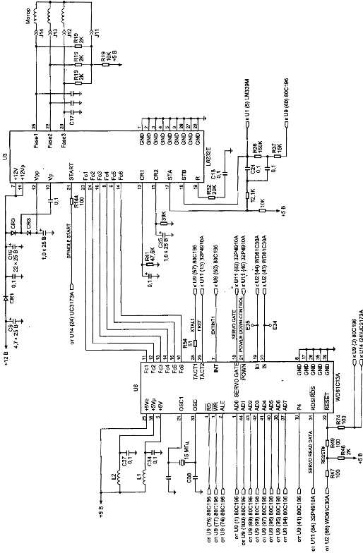
    The layout scheme below is used in WDAC32500 and WDAC33100 drive families and takes into account all ratings and serial numbers of components, but it is also applicable for repair of WDAC2340, WDAC2420, WDAC2540, WDAC2700, WDAC2850, WDAC33100, WDAC31200, WDAC21200, and WDAC31600 drive families if you ignore serial numbers of components and assume that some ratings differ from the values shown in the layout scheme (Figure 5).

    If at HDD power-up its spindle motor does not start you should first make sure that the HDA is operational by connecting it to a known good PCB. If there is no such opportunity you should check the resistance of coils (phases) of the spindle motor, it should correspond to ~ 2 Ohm relatively to middle output; then continue to look for the malfunction on the PCB. (Inability to start a spindle motor frequently results from sticking of magnetic heads to disks).

    In order to check a PCB for failed components, you should remove it from the HDA, connect to an external power supply and position it on the worktable with electronic components facing up. Further operations will require an oscilloscope with sweep frequency up to 50 MHz.

    First of all, you should switch on power and check the feed +5 V and +12V voltages at outputs from the U3 and U6 chips (see layout scheme), check excitation of quartz resonator at outputs 24 and 33 from U6 chip. Then check for presence of clock pulses supplied to the U9 control microprocessor and U11 reading channel to 57 and 13 outputs respectively. After that make sure that there is no RESET signal (active level О). If all the requirements are met then the control microprocessor will start and perform the initialization procedure programming all chips connected to the internal data bus. You can check microprocessor operability indirectly judging by the presence of control pulses: ALE, RD#, WR#, data bus pulses, etc.

    To check the spindle motor control circuit you should trigger 10 ms/div oscilloscope sweep with 2V/div amplification (it is advisable to use 1:10 multiplier). After power-up check for presence of motor start pulses with 11 – 12 V amplitude for three phases (connections J14, J13, J12). The control circuit will try to start the motor for 1 – 2 min., then it will discontinue the attempts. After that you should switch power off/on or send a RESET command by short-circuit of lines 1 and 2 in IDE interface connector using tweezers. If voltage is lower than 10 V for any phase, then U3 chip is malfunctioning. As a result of such failure the spindle motor most likely spins up but remains unable to gain rated rotational speed and, consequently, magnetic heads cannot be shifted from the parking zone. Rotational speed of spindle motor can be controlled using the INDEX pulses at the Е35 control point (if a PCB is connected to the HDA). The frequency of INDEX pulses is ~12 ms, width of INDEX pulses is – 140 nanoseconds. U3 chip is controlled by the U6 synchronization controller chip and the SPINDLE START signal of the spindle motor. For motor start SPINDLE START = 1, for motor stop it is = 0.

    Phase distribution is controlled by the U6 chip through its Fc1 – Fc6 outputs; it uses TTL range of control signals. Feedback of rotational speed is accomplished through the 32Р4910А U11 reading channel chip using the SERVO READ DATA line. In its turn, the U6 synchronization controller chip generates the signal for servo field search (SERVO GATE) for U11 chip.

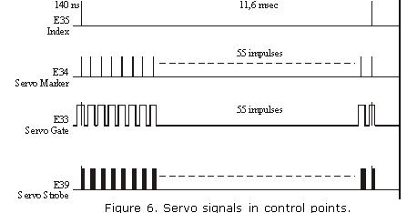
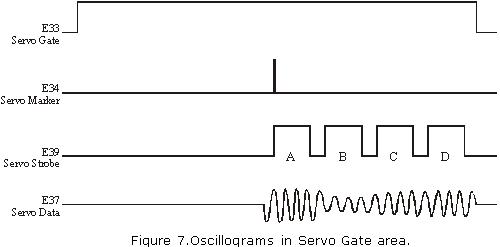
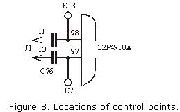
    Servo signals and numbers of control points are indicated in the figure 6 and 7. The signals can be viewed more conveniently using oscilloscope with 100 MHz or greater sweep range since INDEX pulses and servo marker last for about ~140 nanoseconds (it is also advisable to use 1:10 multiplier). Monitoring should be performed using two sources, synchronizing the oscilloscope by INDEX or by servo marker. It may be interesting to watch not only servo signals at the Е37 control point but also data reading signals in general at the Е13 and Е7 control points, where one can see all synchronization fields, sectors, etc. (See figure 8).


    Details on functioning of control microprocessor, data reading channel and spindle motor control chip are available at web sites of Intel, Silicon Systems Incorporation and SGS-Thomson respectively: www.intel.com and www.st.com.

    Read More

    Technologies used for maintaining HDD reliability

    With all the complications HDD manufacturers are constantly trying to make user data storage more reliable. To accomplish that they use various methods and technologies in their drives.

    Figure 5. Control circuit of spindel of HDD (family WDAC 32500 and WDAC 33100)
    S.M.A.R.T. (abbreviated Self-Monitoring, Analysis, and Reporting Technology) is intended to inform hard drive users about the status of its main parameters. Many motherboard BIOSes support analysis of those parameters at computer power-up and if some critical parameter exceeds its emergency limit an informational message is displayed during computer start-up. Of course, it does not mean that the drive will stop functioning, but the user should take some steps in that situation, for example, prepare a backup copy of valuable data. If computer BIOS does not contain an analyzer of S.M.A.R.T. attributes you can use an external diagnostic utility launched from within the operating system. The list of such utilities includes, for instance, SMART Vision available from http://www.acelab.ru/products/pc/traning.html.

    For greater reliability practically all drives use a technology, which allows hiding and relocation of occurring defects immediately during operation. Some peculiarities of its implementation may vary with different drive models; however, they are all based upon the same principle. If the operating system attempts to access a sector, which cannot be read or written to, then the drive will replace it if possible (if there is sufficient reserved space) with a sector from the reserved zone (assign). The table of thus substituted sectors is stored in drive firmware zone and the drive loads it to controller ROM at power-up.

    Impact sensors found in all drives also belong to technologies used for protection against malfunctions. It is a piezoelectric sensor producing an electric pulse at mechanical shock. Filtering of sensor pulses allows identification of obvious impacts. When a drive detects shock action, it parks magnetic heads. One peculiarity of impact sensor installation is the angle of its mounting relative to front case line. It is equal to 45O.

    In recent models manufacturers have began to use widely temperature sensors in PCB and heads’ block. Temperature information is monitored by drive processor and the drive stops operation if the allowed value is exceeded. In some drive models temperature is output as S.M.A.R.T. attribute value and there are programs (usually available from the web pages of HDD manufacturers) which allow viewing it.

    Read More

    HDD malfunctions

     “Nothing is eternal” – that expression applies also to hard disk drives. No matter how reliable a HDD is still it is degraded with time by destructive processes.

     First, a drive is a mechanical and electronic device but all mechanical parts gradually wear out. With time connections between mechanical parts become slack. Numerous ascensions and descents of magnetic heads which occur during each start and stop of magnetic disk rotation destroy the protective layer coating the heads. However, modern manufacturing technology guarantees rather long life for hard drives. Thus, according to the information from the technical manual for operation of Western Digital drives (Caviar BB/JB family) the minimum number of contacts between magnetic heads and disk surface during start/stop (Contact Start/Stop Cycles – CSS) is at least 50000 cycles, while unrecoverable reading errors (Error Rate – Unrecoverable) appear less frequently than once per 10 bytes raised to the 14th power. If we translate those figures into generally understandable terms we receive the following: minimum time before any deterioration in the quality of heads or surfaces because of their contacts provided that the drive is switched on and off ten times daily will be 14 years; and one error will occur during reading of more than 32 TB of data (that approximately corresponds to viewing movies in MP4 format non-stop for 7 – 10 years).

    Still, in real life we frequently face a totally different situation when a brand new drive purchased recently goes out of order after a few months of operation. Numerous drives even do not endure the warranty period defined by their manufacturing factory. We have to note that all manufacturers except for Samsung have decreased that period from 3 years to one. What are the reasons of such situation?

    Normal HDD ageing malfunctions
     During correct operation of a properly assembled drive performed in conformity to all requirements of its Technical Reference Manual with time you can observe normal ageing process. It tells most badly on magnetic disks. First, with time the magnetization of minimum magnetic “prints” – dibits – decreases and a drive has to re-read some portions of disks, which used to read flawlessly, or they even begin to produce reading errors. In the second place, the magnetic layer on disks also deteriorates gathering scratches, chippings, cracks, etc. All of the above cause appearance of BAD sectors.

    The process of normal drive ageing is quite long and usually it takes 3-5 years. We have to note that for a HDD non-stop mode of operation is even more favourable than a mode, when a drive starts and stops frequently. Thus drives function quite long in dedicated servers operating round-the-clock and located in a separate premise or a box with obligatory normal climate control.

    Malfunctions resulting from incorrect mode of operation
     The most frequent cause of HDD malfunctions has to deal exactly with incorrect manner of their operation, its main destructive factors include: overheating, mechanical impacts and voltage jumps of HDD power supply.

    Overheating is caused by insufficient cooling of drive case and PCB. According to the technical reference manual for Western Digital drives (Caviar BB/JB family) the allowed operational drive temperature ranges from 5 С to 550 С provided that air circulates around all the time. The latter condition is determined by the fact that some chips on the control board become much warmer than the above temperature (motor controllers, etc.) and heat dissipation must be arranged for them. Now let us imagine that it is summer time, temperature inside may reach 30 С, within computer case it will grow to the extreme values – by another 20 – 250 С – while there is no normal air circulation because there is only one blow-out fan in the power supply clogged with dust, flat cables inside form a tight knot and the drive is blocked from both sides between a CD drive and FDD. An open computer case at that does not remedy the situation because it does not facilitate air flow around HDD.

    Another important temperature value is its gradient, which should not exceed 200 С per hour during operation and 300 С during downtime. When the latter is exceeded, it is very dangerous for drive mechanics; that phenomenon is called thermal shock. Thus if you bring a HDD during winter time from a store or from a friend (where you had to read some necessary data) and it is frosty outside and 200 С inside, then if you power-up the drive immediately it causes sudden local heating of separate mechanical HDA parts, which may cause micro deformations of precise drive mechanics. Such a drastic temperature drop is very harmful for electronic components, too.

    The same holds true regarding mechanical influence over HDA, i.e. impacts which are also very dangerous for precise mechanical parts of a drive. During operation as described in the previous article, spring-loaded magnetic heads fly at a low height above disks rotating at a rather high speed. An impact against HDA in that situation will cause inevitable vibration of heads which will produce a series of hits against disks, which in turn are sure to cause chipping both on disk surface and on the surface of magnetic heads.

    Very serious danger for HDD electronics is manifested by power supply units powering the whole PC and the drive respectively. In order to make their price lower manufacturers frequently do not install filtering circuitry both in the primary 220 V chain and in secondary circuit. Very frequently rated power does not correspond to the actual values and stabilized voltage turns out to be not so stable although those parameters are strictly regulated for disk drives. Thus, according to the technical reference manual for Western Digital drives (Caviar BB/JB family) allowed power supply voltage is +5 V +- 5% and +12 V +- 10%, allowed fluctuation is 100 mV in +5V circuits and 200 mV in 12 V circuits. Most specialists servicing computer equipment use only voltage meters while testing power supply units, but one should keep in mind that voltage fluctuations, which are an important parameter can be checked with an oscilloscope only.

    Construction-related malfunctions
     Quality of HDDs has decreased lately; that fact is confirmed by reduction of warranty period by many manufacturers. To some extent it is caused by stiff competition between them and the resulting race for production of cheap drives. It is also connected with growing technological standards, a sort of a race for density increase and achievement of higher capacity per disk. As a consequence vendors frequently use in their HDDs solutions, materials and technologies, which have not been thoroughly tested and verified; thus imperfect products appear in the market and then in possession of end users. After some time manufacturers analyze malfunctions of drives returned during their warranty period and attempt to eliminate drawbacks in their construction, but those attempts are not always successful.

    Theoretically such approach to drive design and production may cause problems with any drive part. We can single out the most frequent troubles:

    Bad contact in pin connector between PCB and preamplifier chip connected to magnetic heads’ assembly. The consequences of a poor contact may be quite numerous. First of all, it causes appearance of bad sectors. But those sectors differ from common defects caused by poor surface quality. The difference manifests itself in the fact that the surface remains intact but bad contact causes recording of invalid data to service bytes of some sectors, e.g. to the field containing CRC code of the sector. The problem may also lead to corruption of firmware data, which cannot be restored by the drive itself during the next power-up; besides, there is no user mode for such restoration. Firmware data of a drive can be restored in the factory mode only.

    Poor quality of chips’ soldering at the factory. Such workmanship flaw becomes obvious as a rule approximately after a year of drive operation. It is usually manifested in lack of contact, i.e. after some period of normal operation a drive either switches off and does not start again (“hangs”) or begins to produce knocking sounds with its heads; the latter situation may result in damage to its mechanical parts. Just like the previous flow it may also cause firmware corruption.

    Insufficient quality of chips becoming defective even at heating values, which do not exceed allowed limits. The fault can be repaired by replacing the defective chip with an identical operational one.
    Imperfect construction of fluid dynamic bearings, which causes accumulation of scrap particles in the grease resulting in spindle motor seizure.

    There are also cases when disks are not fixed on a spindle properly, as a result disk beating grows increasingly and causes bearing destruction in spindle motor. Considerable noise begins to accompany drive operation and after some time defective sectors appear because disk beating leads to incorrect reading of some tracks.

    Poor quality of Flash ROM chips, which may lose the firmware code stored therein because of charge leakage when heated. ROM can be overwritten either in a special ROM chip programmer or using the drive itself in the factory mode.

    Errors in drive firmware microcode. Manufacturers do not make public the information about the nature of such errors keeping it secret. However, firmware updates are issued quite regularly. It would be a mistake to believe that the errors do not influence drive’s operability in any way because in some cases they may result in damage to drive mechanics.

    Read More

    Logical structure of disk space

    Considerable part of disk space in modern drives is hidden from users; it contains service data and an area reserved for substitution instead of defective sectors in a HDD. In normal operation mode it is accessible by drive microcontroller only. Users may access the working area frequently called logical disk space and it is exactly the same capacity as the value indicated in the characteristics of a certain model. Access to the working area represented by a continuous chain of logical sectors is performed in LBA notation from 0 to N. Connection between the logical disk space and physical disk format is established through a special program, i.e. a translator, which takes into account physical format, zone allocation as well as defective sectors and tracks to be skipped during operation.

     Access to firmware zone is possible only in a special drive operation mode, i.e. factory mode. A drive is switched into that mode by a key command opening access to an additional set of factory commands. Those commands are used for such operations as reading/writing of firmware zone sectors, obtaining a map with locations of modules and tables in firmware zone, access to zone allocation table, conversion of LBA into PCHS and vice versa, launch of low-level format, reading/writing to/from Flash ROM and some other actions.

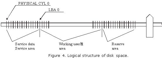
     In the process of HDD design developers define firmware data required for drive operation as well as the number of cylinders occupied by firmware; therefore zero logical cylinder is the first free cylinder following the last cylinder occupied by firmware area. (See figure 4.) The structure of disk space may vary with different HDD models.

     Figure 4. Logical structure of disk space.

    Read More

    Two mechanisms of defect relocation

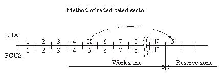
    When the substitution (Assign) mechanism is used in a drive the latter records to the ID field of a BAD sector the flag of the relocated sector and writes to the data field the number of the reserved sector, i.e. the one, which should be accessed for data recording or reading. As a rule, it is the first available sector after user data area. (figure 2.).

    Figure 2. Method of rededicated sector.
    During data read/write operations accessing the defective sector drive controller will read the flag and assigned address and reposition the heads to the reserved zone in order to perform reading/writing from/to a good sector. Defective sectors in that case will disappear, but the drive will perform positioning to the reserved area each time it has to address a defective sector. The procedure is accompanied with clicking sounds and slight slow-down. The “Assign” procedure allows relocation only for defects in data fields. Errors pertaining to corruption of ID fields or servo fields cannot be relocated using the “Assign” method.

    Another mechanism used for hiding defective sectors at manufacturing factories is skipping of defective sectors. When that method is used, the defective sector is skipped, its number is assigned to the following sector (and so on), and the last sector is shifted to the reserved zone. (figure 3.).

    Figure 3. Method of missing sector.
    Such method of sector hiding disrupts the continuous integrity of low-level format; the system of LBA conversion to PCHS should also take into account BAD sectors while skipping them. Therefore the method requires obligatory recalculation of translator tables and low-level formatting making it impossible to preserve user data if the method is employed. Exactly for that reason the said method of relocation is applied only in special factory mode of drive operation. It is used in the FUJFMT.EXE utility designed for relocation of defects in FUJITSU drives.

    Read More

    Firmware data (service information)

    Firmware data is necessary for functioning of internal HDD circuits and as a rule it remains hidden from users.

    Firmware data can be subdivided into the following types:
     

    Servo information or servo fields;
     Low-level format;
     Resident firmware microcode (operational programs);
     Configuration tables and settings;
     Tables of defects.

     
    Servo fields are necessary for operation of a servo system used by the driving assembly of magnetic heads in a HDD; they serve for heads’ positioning and keeping them precisely over a defined track. Servo fields are recorded during the manufacturing process to an already assembled HDA through special service openings in its case. The openings are subsequently closed with sticky labels that read: Warning! DO NOT OPEN. The recording is actually performed using drive’s own heads in a special high-precision instrument – servo writer.  Relocation of heads’ positioner is achieved through a motion of a special pusher of the servo writer using steady steps much smaller than the intervals between tracks.

     Firmware (microcode) of the control microprocessor is a collection of programs required for operation of HDD components. Here belong the programs used for initial diagnostics, control of spindle motor rotation, data exchange with disk controller, buffer RAM, etc. In most HDD models firmware microcode is stored within internal microcontroller ROM; some models employ external Flash ROM. In some HDD models a part of firmware programs is recorded to magnetic disk in a special firmware zone while ROM contains the programs used for initialization, and positioning together with primary loader reading the firmware data from magnetic disk to RAM. Since actual firmware modules are first loaded to RAM before execution they have been called resident modules.

     Manufacturers of hard drives record some firmware portions on disk surface not only for purposes of ROM space saving, but also to enable its easy replacement if the manufacturing process or drive operation reveal any errors in a microcode. Internet pages of most manufacturers contain links to utilities used for such updates. Overwriting disk firmware is much easier than unsoldering of hard-programmed microcontrollers. We can remember how Western Digital had to recall a large number of its drives back to factory several years ago…

     Low-level format. Track beginning is identified by an index pulse. Each track is subdivided into data sectors and servo fields. Format of each sector consists of an ID field, data field, synchronization zones and spaces. The beginning of each sector contains a synchronization zone used for phasing and synchronization of data strobe. ID field contains an address marker, physical sector address, flag byte and CRC bytes.

     Format without identifiers has become popular recently. When manufacturers employ such method of data placement along a track ID fields are not used at all (thus increasing available drive capacity). Instead they use a system of servo fields directing to physical sectors on a track. At that reading/writing of all sectors on a track is performed simultaneously (in one disk revolution) to/from RAM containing an image of the read/written track. Thus for reading just one sector a drive copies a whole track to RAM and reading of all subsequent sectors (if necessary) is performed from drive RAM instead of disk surface. Identical operations are performed during recording. During sector recording a drive reads a track, modifies it in RAM and writes the whole track back to disk.

     Configuration tables and settings of hard drives contain information about logical and physical structure of disk space. Those tables enable PCBs, which are identical for the whole drive family, to self-adjust for a certain drive model. As a matter of fact, during design of a certain model like, for example, a 80 Gb drive based on two disks it allows to produce automatically a “half-size” model with 40 Gb capacity based on one disk and “quarter-size” model with 20 Gb capacity based on one side only. Thus a manufacturer can offer a greater number of models with varied capacity for the market without considerable R&D expenses. Besides, junior models can use disks, which for some reasons are unsuitable for full-size models. E.g. “half-size” models can successfully use magnetic disks with defects on one of their surfaces, etc.

     Tables of defects. Modern technology of magnetic disks production does not allow their defect-free manufacture. Heterogeneity of media material, polishing defects, admixtures during magnetic layer application, etc. result in appearance of areas, where data recording or reading end in errors.

     Earlier drives with ST506/412 interface displayed the table of defective tracks as a label on HDA case and any drive had some reserved space, e.g. HDD ST225 (20 Mb) had actual capacity of 21,5 Mb, i.e. 1,5 Mb extra were allocated for defective sectors and tracks. Modern HDDs also have extra capacity, but it is hidden from users and only drive microcontroller can access it. A portion of that extra space is allocated to HDD firmware, configuration tables, S.M.A.R.T. counters, factory information about a HDD, tables of defects, etc. The remaining part is held in reserve for substitution of defective sectors with the reserved ones.

     Tables of defects are filled by the manufacturer during internal factory testing. Numbers of all discovered BAD sectors are added into a table. Such procedure is called updating (relocation) of defects (UPDATE DEFECT). After that if a defective sector is addressed during work with a HDD, the drive itself will redirect the request to a reserved sector. Therefore all modern drives newly arriving from the manufacturing factories have no defective sectors.

     Most HDD models have two tables of defects: Primary or P-List and Grown or G-List. Primary table is filled at the factory during internal testing – SELFSCAN (intelligent burn-in). Grown list is not filled at the factory; it is designed for addition of defects which appear during drive operation. To enable that functionality, the list of user commands practically in all HDDs contains the “assign” command replacing a defective sector with a reserved one. The command is used by numerous test utilities including those recommended by the manufacturers for operations over drives with BAD sectors. Western Digital drives have a Data Lifeguard system, which performs automatic substitution of defective sectors while a drive is idle. In order to perform the procedure, a drive self-tests its surfaces and transfers user data to a reserved sector marking at that defective sector as BAD; the mechanism of defect relocation is identical to the “assign” command. Manufacturers of Fujitsu, Quantum, Maxtor, and IBM drives implemented a mechanism of automatic defect relocation during the recording process. Thus if data is recorded to a defective sector, a drive itself will redirect such request to the reserved zone marking at that the defective sector as BAD and adding its number to G-List. Among specialized utilities used for relocation of BAD sectors we can note FUJFMT.EXE for Fujitsu drive, WDDIAG.EXE for Western Digital drives, ShDiag.exe offered by Samsung, etc.

    Read More