Slide 1289: The first thing a hard drive will do after it receives power is check for a return status from it’s chips to make sure the electronics are functioning. Then the drive will begin the self-check of its parts and wait for a return status. If both status checks are returned then the drive continues on to the next step and spin up the spindle.
Slide1389: The drive begins to spin the spindle or as you would see, the platters begin to revolve. When the platters begin to revolve the air flow around the platter creates a force that is called an air bearing. This air bearing will fling off debris on the platters such as any dust particles or metal fragments from the standard operation of the drive. This air bearing also causes the plastic locking arm mechanism to move out of the way as soon as there is enough air flow for the head to float. Without that airflow the arm is locked in place and will not move over the platter. This is a way to protect the platter from the head touching the platter and causing physical damage. The opposite is true during a power down. When power is cut to the drive, during the last revolutions of the motor, it generates enough power to move the head back to it park position. Because of this, as you can imagine, if you get enough power on and power off cycles in a row it is possible for the head to be stuck in the center of the platter and never to be parked correctly causing several types of damage. In certain 80 gig laptop 2.5″ inch drives it is common for the head to be stuck to the center of the platter, never having parked and keeping the platters from spinning. In most cases there is very little damage if the drive is opened and manually turned slow enough not to damage the head, and the data can be recovered, obviously never using this drive again.
Slide 1483: At this point, if the all has proceeded correctly the air bearing will allow the head to float over the platter allowing it to move freely without scratching the surface of the platter.
Slide 1545: At this point, if the head is reading the Servo Timing info from the platter and relaying it to the circuitry so the controller knows the geographic information for the placement of data. (See previous speech at Defcon 14 for discussion about Voice Coil and stepping motors to understand the servo info).
Slide 1679: At this point the head moves to the System Area (SA) of the platters and reads the content that it requires as well as any additional firmware and overlays.
Most of the time, the system area is on the outer tracks – the extreme outer edge. This is chosen by the manufacturer but is most common on the outside on 3.5 and is sometimes written to the inside tracks on a 2.5″ inch drive.
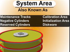
System Area Information Common Names
1. System Area
2. Maintenance Tracks
3. Negative Cylinders
4. Reserved Cylinders
5. Calibration Area
6. Initialization Area
7. Diskware


