For replacing the circuit boards on the hard disk drive, just simple unscrew PCB and swap won’t help any more!
My WD hard drive PCB’s chip has fried. I have already purchased a donor PCB to try to salvage the drive; however, there was no life breathed into it. The hard drive still didn’t spin and was unrecognizable by the computer.
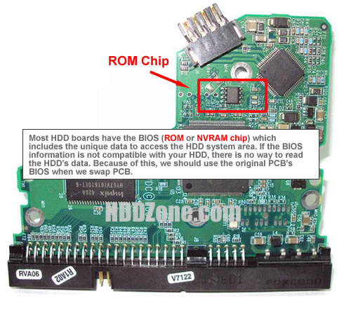
A common misconception is that a damaged printed circuit board (PCB) may be simply replaced during data recovery procedures by an identical PCB from a healthy drive. While this may work in rare circumstances on hard disk drives manufactured before 2003, it will not work on newer drives. Electronics boards of modern drives usually contain drive-specific adaptation data (generally a map of bad sectors and tuning parameters) and other information required to properly access data on the drive. Replacement boards often need this information to effectively recover all of the data. The replacement board may need to be reprogrammed. Some manufacturers (Seagate, for example) store this information on a serial EEPROM chip (ROM/BIOS), which can be removed and transferred to the replacement board.

Each hard disk drive has what is called a system area or service area; this portion of the drive, which is not directly accessible to the end user, usually contains drive’s firmware and adaptive data that helps the drive operate within normal parameters. One function of the system area is to log defective sectors within the drive; essentially telling the drive where it can and cannot write data.
The sector lists are also stored on various chips attached to the PCB, and they are unique to each hard disk drive. If the data on the PCB do not match what is stored on the platter, then the drive will not calibrate properly. In most cases the drive heads will click because they are unable to find the data matching what is stored on the PCB.

