The ever-changing storage system technology

Today’s storage technology encompasses all sorts of storage media. These could include WORM systems, tape library systems and virtual tape library systems. Over the past few years, NAS and SAN systems have provided excellent reliability. What is the difference between the two?

• NAS (Network Attached Storage) units are self-contained units that have their own operating system, file system, and manage their attached hard drives. These units come in all sorts of different sizes to fit most needs and operate as file servers.

• SAN (Storage Area Network) units can be massive cabinets – some with 240 hard drives in them! These large 50+ Terabyte storage systems are doing more than just powering up hundreds of drives. These systems are incredibly powerful data warehouses that have versatile software utilities behind them to manage multiple arrays, various storage architecture configurations, and provide constant system monitoring.

For some time, large-scale storage has been out reach of the small business. Serial ATA (SATA) hard disk drive-based SAN systems are becoming a cost-effective way of providing large amounts of storage space. These array units are also becoming main stream for virtual tape backup systems – literally RAID arrays that are presented as tape machines; thereby removing the tape media element completely.

Other storage technologies such as iSCSI, DAS (Direct Attached Storage), Near-Line Storage (data that is attached to removable media), and CAS (Content Attached Storage) are all methods for providing data availability. Storage architects know that just having a ‘backup’ is not enough. In today’s high information environments, a normal nightly incremental or weekly full backup is obsolete in hours or even minutes after creation. In large data warehouse environments, backing up data that constantly changes is not even an option. The only method for those massive systems is to have storage system mirrors – literally identical servers with the exact same storage space.

How does one decide which system is best? Careful analysis of the operation environment is required. Most would say that having no failures at all is the best environment – that is true for users and administrators alike! The harsh truth is that data disasters happen every day despite the implementation of risk mitigation policies and plans.

Read More

Linux File Management and Viewing

File and Directory management

apropos
Search the whatis database for files containing specific strings.

bdflush
Kernel daemon that saves dirty buffers in memory to the disk.

cd
Change the current directory. With no arguments “cd” changes to the users home directory.

chmod
chmod <specification> <filename> – Effect: Change the file permissions.
Ex: chmod 751 myfile        Effect: change the file permission to rwx for owner, re for group
Ex: chmod go=+r myfile        Effect: Add read permission for the owner and the group
character meanings u-user, g-group, o-other, + add permission, – remove, r-read, w-write,x-exe
Ex: chmod a +rwx myfile        Effect: Allow all users to read, write or execute myfile
Ex: chmod go -r myfile        Effect: Remove read permission from the group and others
chmod +s myfile – Setuid bit on the file which allows the program to run with user or group privileges of the file.
chmod {a,u,g,o}{+,-}{r,w,x} (filenames) – The syntax of the chmod command.

chown
chown <owner1> <filename> Effect: Change ownership of a file to owner1.

chgrp
chgrp <group1> <filename> Effect: Change group.

cksum
Perform a checksum and count bytes in a file.

cp
cp <source> <destination> Copy a file from one location to another.

dd
Convert and copy a file formatting according to the options. Disk or data duplication.

dir
List directory contents.

dircolors
Set colors up for ls.

file
Determines file type. Also can tell type of library (a.out or ELF).

find
Ex: find $Home –name readme Print search for readme starting at home and output full path.

How to find files quickly using the find command:
Ex: find ~ -name report3 –print

* “~” = Search starting at the home directory and proceed through all its subdirectories
* “-name report3” = Search for a file named report3
* “-print” = Output the full path to that file

install
Copy multiple files and set attributes.

ln
Make links between files.

locate
File locating program that uses the slocate database.

losetup
Loopback device setup.

ls
List files. Option -a, lists all, see man page “man ls”
Ex: “ls Docum Projects/Linux” – The contents of the directories Docum and Projects/Linux are listed.
To list the contents of every subdirectory using the ls command:

1. Change to your home directory.
2. Type: ls -R

mkdir
Make a directory.

mknod
Make a block or character special file.

mktemp
Make temporary filename.

mv
Move or rename a file. Syntax: mv <source> <destination> Ex: mv filename directoryname/newfilename

pathchk
Check whether filenames are valid or portable.

pwd
Print or list the working directory with full path (present working directory).

rm
Ex: “rm .*” – Effect: Delete system files (Remove files) –i is interactive option.

rmdir
rmdir <directory> – Remove a directory. The directory must be empty.

slocate
Provides a secure way to index files and search for them. It builds a database of files on the system.

stat(1u)
Used to print out inode information on a file.

sum
Checksum and count the blocks in a file.

test
Check file types and compare values.

touch
Change file timestamps to the current time. Make the file if it doesn’t exist.

update
Kernel daemon to flush dirty buffers back to disk.

vdir
List directory contents.

whatis
Search the whatis database for complete words.

wheris
Locate the binary, source and man page files for a command.

which
Show full path of commands where given commands reside.

File viewing and editing

ed
Editor

emacs
Full screen editor.

gitview
A hexadecimal or ASC file viewer.

head
head linuxdoc.txt – Look at the first 10 lines of linuxdoc.txt.

jed
Editor

joe
Editor

less
q-mandatory to exit, Used to view files.

more
b-back q-quit h-help, Used to view files.

pico
Simple text editor.

tail
tail linuxdoc.txt – Look at the last 10 lines of linuxdoc.txt.

vi
Editor with a command mode and text mode. Starts in command mode.

File compression, backing up and restoring

ar
Create modify and extract from archives.

bunzip2
Newer file decompression program.

bzcat
Decompress files to stdout.

bzip2
Newer file compression program.

bzip2recover
Recovers data from damaged bzip2 files.

compress
Compress data.

cpio
Can store files on tapes. to/from archives.

dump
Reads the filesystem directly.

gunzip
unzip <file> – unzip a gz file.

gzexe
Compress executable files in place.

gzip
gzip <file> – zip a file to a gz file.

mt
Control magnetic tape drive operation.

tar
Can store files on tapes.
Usage: tar cvf <destination> <files/directories> – Archive copy groups of files
Ex: tar /dev/fdo temp Effect: Copy temp to drive A:

uncompress
Expand data.

unzip
unzip <file> – unzip a zip file. Files ending in “.gz” or “.zip” are compressed.

zcat
Used to restore compressed files.

zcmp
Compare compressed files.

zdiff
Compare compressed files.

zforce
Force a .gz extension on all gzip files.

zgrep
Search possibly compressed files for a regular expression.

zmore
File filter for crt viewing of compressed text.

znew
Recompress .z files to .gz files.

zip
zip <file> – make a zip file.

Extra control and piping for files and other outputs

basename
Strip directory and suffix information from filenames.

cat
Ex: cat < filename — Effect: put keyboard input into the file. CTRL-D to exit (end).

cmp
Compare two files.

colrm
Remove columns from a file.

column
Columnate lists.

comm
Ex: comm file1 file2 — Effect compare the contents of file1 and file2 produces 3 columns of output. Lines in the first file, lines in second file, lines in both files.

csplit
Split a file into sections determined by context lines.

cut
Remove sections from each line of files.

diff
Show the differences between files. Ex: diff file1 file2

diff3
Find differences between 3 files.

dirname
Strip the non-directory suffix from a filename.

echo
Display a line of text.

egrep
Similar to grep -E, compatible with UNIX egrep.

expand
Convert tabs to spaces.

expr
Evaluate expressions.

false
Do nothing. Exit with a status indicating failure.

fgrep
Same as grep -F.

fold
Wrap each input line to fit in specified width.

join
Join lines of two files in a common field.

grep
grep pattern filename.
Ex: grep ” R ” — Effect: Search for R with a space on each side
Ex: ls –a |grep R — Effect: List all files with an R in them or their info listing.

hexdump
asc, decimal, hex, octal dump.

logname
Print user’s login name.

look
Display lines beginning with a given string.

mkfifo
Create named pipes with the given names.

nl
Write each file to standard output with line numbers added.

od
Dump files in octal and other formats.

patch
Apply a diff file to an original.

paste
Combines from 2 or more files. Ex: paste file1 file 2

printf
Print and format data.

rev
Reverses lines in a file.

script
Make a typescript of a terminal session.

sdiff
Find differences between 2 files and merge interactively.

sed
A stream editor. Used to perform transformations on an input stream.

sleep
Delay for a specified amount ot time.

sort
Sort a file alphabetically.

split
Split a file into pieces.

strings
Print the strings of printable characters in files.

tac
Concatenate and print files in reverse.

tee
Read from standard input and write to standard output and files.

tr
Translate or delete characters.

true
Do nothing. Exit with a status indicating success.

tsort
Perform topological sort.

ul
Do underlining.

unexpand
Convert tabs to spaces.

uniq
Remove duplicate lines from a sorted file.

uudecode
Used to transform files encoded by uuencode into their original form.

uuencode
Encode a binary file to be sent over a medium that doesn’t support non-ASC data.

wc
Count lines, words, characters in a file. Ex: wc filename.

xargs
Build and execute command lines from standard input.

yes
Output the string “y” until killed.

Read More

Linux Filesystem Management

badblocks
Used to search a disk or partition for badblocks.

cfdisk
Similar to fdisk but with a nicer interface.

debugfs
Allows direct access to filesystems data structure.

df
Shows the disk free space on one or more filesystems.

dosfsck
Check and repair MS-Dos filesystems.

du
Shows how much disk space a directory and all its files contain.

dump
Used to back up an ext2 filesystem. Complement is restore.

dumpe2fs
Dump filesystem superblock and blocks group information. Ex: dumpe2fs /dev/hda2

e2fsck
Check a Linux second extended filesystem.

e2label
Change the label on an ext2 filesystem.

exportfs
Used to set up filesystems to export for nfs (network file sharing).

fdisk
Used to fix or create partitions on a hard drive.

fdformat
Formats a floppy disk.

fsck
Used to add new blocks to a filesystem. Must not be run on a mounted file system.

hdparm
Get/set hard disk geometry parameters, cylinders, heads, sectors.

mkfs
Initializes a Linux filesystem. This is a front end that runs a separate program depending on the filesystem’s type.

mke2fs
Create a Linux second extended filesystem.

mkswap
Sets up a Linux swap area on a device or file.

mount
Used to mount a filesystem. Complement is umount.

rdev
Query/set image root device, swap device, RAM disk size of video mode. What this does is code the device containing the root filesystem into the kernel image specified.

rdump
Same as dump.

rmt
Remote magtape protocol module.

restore

Used to restore an ext2 filesystem.

setfdprm
Set floppy drive parameters.

swapoff(8)
Used to de-activate a swap partition.

swapon(8)
Used to activate a swap partition.

sync

Forces all unwritten blocks in the buffer cache to be written to disk.

tune2fs
Adjust tunable filesystem parameters on second extended filesystems.

umount
Unmounts a filesystem. Complement is mount.

Read More

Linux File Formats

linux File formats/etc/crontab
The syntax of each line in this file is:

minute, hour, day of month, Month, day of week, (user name), command

/etc/fstab
Columns are: device file to mount, directory to mount on, filesystem type, options, backup frequency, and fsck pass number (To specify the order in which filesystems should be checked on boot; 0 means no check.) The noauto option stops this mount from being done automatically on boot. Below is a detailed list of what is on each column.

1. The name of the device such as “/dev/hda1”
2. The mount point. Use “/” for root. Other typical mount points are “/dos” for DOS, “swap” or “none” for the swap partition, and “/mnt/floppy” for “/dev/fd0” (the floppy drive).
3. The type of filesystem. They are: mini, ext, ext2(linux native), xiafs, msdos, hpfs, ntfs, fat32, iso9660(CD-ROM), NFS, swap (for swap space).
4. The mount options for use with the filesystem. Each filesystem type has different mount options. Read the mount man page to see possible options. ro= read only, user- allows normal users to mount the device.
5. The frequency the filesystem needs to be dumped (backed up) by the dump command. For ext2, normally make it 1, for others make it 0. 0 or nothing means it is not dumped. If 1, it is backed up during a system backup.
6. A number telling the order in which the filesystems should be checked at reboot time by the fsck program. Your root should be 1, others are in ascending order or 0 to not be checked.

/etc/hosts
Sets up host address information for local use. The format is:

IPaddress name1 name2…

/etc/inetd.conf
Sets the services under the inetd daemon. The fields of this file are:

1. service name
2. socket type
3. protocol
4. wait or nowait
5. user
6. server program name
7. server program command line arguments

/etc/inittab
Sets the init configuration. An entry in the inittab file has the following format:

id:runlevels:action:process

/etc/lilo.conf
Tells LILO how to boot
The lilo.conf file below is for a system which has a Linux root partition on /dev/hda1 and a MS-DOS partition on /dev/hda2. See the “How Linux Works” guide and the “Linux User’s Guidel” for more information.

boot = /dev/hda        # Tell LILO to install the boot loader on the /dev/hda disk boot record
vga = normal        # Set a normal video mode
delay = 60        # The time in tenths of seconds to press <SHIFT> to get the LILO prompt
# Equivalent would be “prompt” on one line, and “timeout=60” on
# another line.
default=msdos        # Sets the default boot to DOS, Without this line, the default is the first stanza
install = /boot/boot.b        # The file containing the boot sector to use
compact        # Have LILO perform some optimization.
map = /boot/map        #Specifies the map file LILO creates when installed
# Section for Linux root partition on /dev/hda2.
image = /vmlinuz        # Location of kernel
label = linux         # Name of the OS that is displayed in the LILO boot menu
root = /dev/hda1         # Location of root partition, if this isn’t here the kernel image must have
# this set using the rdev command
read-only         # Mount read only on startup, Can also be set by rdev
# Section for MSDOS partition on /dev/hda1.
other = /dev/hda2         # Location of partition
table = /dev/hda         # Location of partition table for /dev/hda2
label = msdos         # Name of OS (for boot menu)

if the command “vga= ask” is given, LILO will prompt the user for a video mode at boot time.

/etc/passwd
The file has one line per username, and is divided into seven colon-delimited fields:

1. Username.
2. Password, in an encrypted form.
3. Numeric user id.
4. Numeric group id.
5. Full name or other description of account. This is called gecos.
6. The user’s home directory.
7. The user’s login shell (program to run at login).

The format is explained in more detail on the passwd manual page.

/usr/X11R6/lib/X11/XF86Config
The main XFree86 configuration file. Type “man XF86Config”

* The first section is “Files”
RgbPath        Sets the path to the X11R6 RGB color database
FontPath        Sets the path to a directory containing X11 fonts
* The second section is “ServerFlags”, all lines are commented out
* The third section is “Keyboard”
* The fourth section is “Pointer”
Protocol        Specifies the mouse protocol
Device        Specifies the device file by which the mouse can be accessed.

* The fifth section is “Monitor” which specifies the characteristics of your monitor
ModeLine        Specifies resolution modes for your monitor

The file, VideoModes.doc describes in detail how to determine the ModeLine values for each resolution mode. Two files, modeDB.txt and Monitors,may have ModeLine information for your monitor. They are located in /usr/X11R6/lib/X11/doc.

* The sixth section is “Screen” describing the video/monitor card configuration for the particular server.
The Driver line specifies the X server that you will be using. Valid Driver values are:

_ Accel: For the XF86 S3, XF86 Mach32, XF86 Mach8, XF86 8514,

XF86 P9000, XF86 AGX,and XF86 W32 servers;
_ SVGA: For the XF86 SVGA server;
_ VGA16: For the XF86 VGA16 server;
_ VGA2: For the XF86 Mono server;
_ Mono: For the non-VGA monochrome drivers in the XF86 Mono and XF86 VGA16 servers.
Be sure that /usr/X11R6/bin/X is a symbolic link to this server.

The Device line specifies the Identifier of the Device section that corresponds to the video card to use for this server. Above, we created a Device section with the line Identifier “#9 GXE 64”

Therefore, we use “#9 GXE 64” on the Device line here. Similarly, the Monitor line specifies the name of the Monitor section to be used with this server. Here, “CTX 5468 NI” is the Identifier used in the Monitor section described above.

*Subsection “Display” defines several properties of the XFree86 server corre-sponding to your monitor/video card combination. The XF86Config file describes all of these options in detail. Most of them are not necessary to get the system working.

The options that you should know about are:

o_ Depth. Defines the number of color planes; that is, the number of bits per pixel. Usually, Depth is set to 16. For the VGA16 server, you would use a depth of 4, and for the monochrome server a depth of 1. If you use an accelerated video card with enough memory to support more bits per pixel, you can set Depth to 24, or 32.

o _ Modes. This is the list of mode names that have been defined using the ModeLine directive(s) in the Monitor section. In the above section, we used ModeLines named “1024×768”, “800×600”,and “640×48″0. Therefore, we use a Modes line of

Modes “1024×768” “800×600” “640×480”

The first mode listed on this line is the default when XFree86 starts. After XFree86 is running, you can switch between the modes listed here using the keys Ctrl – Alt –Numeric + and Ctrl – Alt – Numeric – .
It might be best, when you initially configure XFree86, to use lower resolution video modes like 640×480, which tend to work with most systems. Once you have the basic configuration working, you can modify XF86Config to support higher resolutions.

o_ Virtual. Set the virtual desktop size. XFree86 can use additional memory on your video card to extend the size of the desktop. When you move the mouse pointer to the edge of the display, the desktop scrolls, bringing the additional space into view. Even if you run the server at a lower video resolution like 800×600, you can set Virtual to the total resolution that your video card can support. A 1-megabyte video card can support 1024×768 at a depth of 8 bits per pixel; a 2-megabyte card 1280×1024 at depth 8, or 1024×768 at depth 16. Of course, the entire area will not be visible at once, but it can still be used. The Virtual feature is rather limited. If you want to use a true virtual desktop, fvwm and similar window managers allow you to have large, virtual desktops by hiding windows and using other techniques, instead of storing the entire desktop in video memory. See the manual pages for fvwm for more details about this. Some Linux systems use fvwm by default.

o_ ViewPort. If you are using the Virtual option that is described above, ViewPort sets the coordinates of the upper-left-hand corner of the virtual desktop when XFree86 starts up. Virtual 0 is often used. If this is unspecified, then the desktop is centered on the virtual desktop display, which may be undesirable to you.

Read More

CD Data Recovery

It is not the end of the world. It is no longer the end of your life or the world if you had just lost your favorite photos, music files or any important information. With this method – CD Data Recovery, your lost information can be completely recovered in most cases.

This method can help you to recover your data if you have lost your data on a CD-R, CD-RW or DVD. What are the reasons for data lost or failure on a CD?

1)  Due to virus attacks.
2)  Lost partitions.
3)  Configuration errors.
4)  The performance of the drives when reading the files to the CD.

The above reasons make the recovery of data on a CD often complicated, but rest assured that there is always hope for recovering your lost data.

There are some software that are able to help you to recover your data from a CD. Some of them are fully automatic and simple rewrites the lost files back to the hard drive, recovering missing or lost data from documents, images, and even applications.

They are cheap with high level of success. It also does not overwrite the files on the CD, which often can cause problems.

Another software such as “Multi Data Rescue” are used by many IT experts to recover their lost data from CDs. This program is usable in the Windows interface and is considered to be very user friendly. It can be used to recover data from CDs and DVDs, supports digital media recovery, and can even recover data from memory cards and USB related data issues.

With so many programs in the marketplace, CD data recovery is no longer about trying the impossible but rather about getting your lost files and documents back as soon as possible.

Recovering in a quick manner is what all it matters right now though it is no longer a concern how much data had been lost.

Having said that, technology can be both a blessing and hindrance at times, but in the end, there are always tools to help us out. There will more and more advanced programs to help you to recover your data fast.

Read More

Flash Data Recovery

Flash disks have become ubiquitous media for everything from computer data, mp3 players and digital cameras. It has replaced the floppy disk as means to carry data around. Flash disks are solid-state devices and, therefore, have no moving parts. Plugging it into the USB drive, the flash drive is automatically recognized by the computer without any need of installing additional software. With expected lifetime measured in hundreds of thousands of write-erase cycles, flash drives are expected to last up to 10 years. That’s more than twice that of a hard disk.

Flash disk portability however leads to a higher probability of damage due to environmental factors. Aside from the regular causes of drive failure, flash drives could get wet in the rain, the casing could shatter when it is accidentally dropped, or it could be damaged while inside the camera.

The difference in data storage between a flash drive and a regular hard drive or a floppy is due to the data residing on a chip. This allows for a truly random access across the whole media. In fact, the disk access algorithm makes sure that the data is spread evenly among data sectors with the use of “wear leveling algorithm.” The flash disk has a finite number of write/erase cycles. If it were to keep on writing to a particular sector, that sector would literally wear out from use much earlier than the other sectors. The wear leveling algorithm ensures that the sectors wear out evenly. And also because of the wear leveling algorithm, when a data sector wears out, the rest of the disk is sure to quickly follow.

In some instances, the camera cannot distinguish between the file system on the flash disk and force a format. Early flash disks used FAT12 or FAT16. FAT32 is used by current generation large capacity flash disks. If the digital camera fails to detect the flash drive’s capacity it might wrap around data while writing the photo and over-write system areas.

There are times the flash disk could not be read by the computer. Though attributed to the computer, this is an error caused by the camera or MP3 player OS. Unplugging the drive while it’s writing data may also cause a corrupted flash drive.

Flash data recovery in most ways is like recovery from any other media using FAT. The only difference is the location of the media files. The data can be recovered by using data recovery tools capable of reading FAT. Typically for cameras, the file structure is fixed. The camera’s limited operating system will write to a specific folder on the directory. The same goes with MP3 players. The mp3 files have to be located in a specific directory for the mp3 player to locate and play them. Some specialized tools look for the specific folder where the media files should be.

Treating all the data on the disks as data files, disk recovery programs or other utilities are capable of correcting any errors. The Windows CHKDSK utility treats the disk like any other drive.

In case of lost data, flash data recovery is just like recovering data from any other medium but, again, with slight differences. Because the data is stored differently, there are more tools available for flash data recovery. Available tools and utilities include flash data recovery specializing in picture files or mp3 music files. Other specialized utilities which can be used for flash data recovery are those which specifically recover data from FAT drives. In case the pictures were accidentally erased from the camera, these utilities are also able to recover them and recover the picture.

In some cases, data recovery can be even simpler. A flash disk recovered from a lake or which got wet from the rain may still be usable after making sure that the circuitry is completely dry. And a flash disk with a broken case might even be usable. In both instances, it would be good to test first by plugging it in. If the drive is still readable, just copy the files before deciding what to do with the flash drive.

Flash drives’ typical failures:

When we are coming to the topic of flash data recovery, it’s very necessary for us to have a general view of the typical failures of flash drives such as the SD, CF, SM ,MMC, XD, USB Pendrive, MemoryStick, etc.

It’s believed 90% of flash drives’ failures are due to corruption in the lookup tables which convert logical addresses (what your computer sees) to physical addresses (what the controller sees). Other failures are usually caused by controller failures, power surges, and worn or broken solder joints.

NAND memory has many quarks.
* Each block is only good for a finite number of writes after which bit errors occur, for example the word “flash” may become “slash”.
* Data can be read in pages (2K bytes) but must be written in blocks (128K bytes).
* Before a write can occur the block must be erased, if power is lost before a write completes the sector remains erased.

Lookup tables

Lookup table is an array or matrix of data that contains items that are searched. Lookup tables may be arranged as key-value pairs, where the keys are the data items being searched (looked up) and the values are either the actual data or pointers to where the data are located. Sometimes, lookup tables contain only data items (just values, not key-value pairs).

Each word (two bytes) contains the block number which holds that sectors data. For example 0×001A is the block number for sector 0, 0×0419 is the block number for sector 1, etc. If the block numbers are incorrect the controller won’t know where the actual data is stored. In this example some of the block numbers are incorrect because of bit errors caused by an aging NAND chip. Some controllers may automatically detect the error and prevent further writes. In this case the user may get an error message asking them to format the drive.
damaged-translation-table
In this example the flash drive was unplugged before a write operation on the lookup table completed leaving the table filled with 0xFFFF from the erase cycle. The user may be prompted to insert removable media, the drive may be displayed as 0MB in size, if the drive is listed it may be shown as an unknown device.

As NAND memory ages bits inside a block can become stuck, newer high density MLC chips are plagued by this problem. To combat this controller manufactures use ECC (Error Correcting Code) to fix a limited number of bit errors. Once the number of correctable bits per sector is exceeded flash drives may act strangely for example frequent file system corruption may occur or the drive will stop working. In these cases I’ll often see color shift in pictures, half the image will be normal and the other half will be a different tint. This is because part of the image was stored in a good block while the other part was in a bad block with sticky bits.

Weak Solder Joints

Wear and tear on the drive can cause solder joints on the NAND memory chip or controller to weaken. If the drive is recognized the total capacity will only be a few megabytes. If you connect the drive while applying LIGHT PRESSURE to the controller and NAND memory you may be able to retrieve the data. Remember, weak solder joints account for LESS THAN 10% of failures. DON’T APPLY MORE PRESSURE if this doesn’t work, you may damage the NAND memory chip if you press too hard.

Hacked USB Flash Drives

Some unbranded or counterfeit flash drives are hacked to display the wrong drive size using the manufactures mass production tool and then sold as larger capacity drives. For example a flash drive with a 4GB NAND chip will report itself as 8GB drive. These drives often work until the user starts to fill the drive with data after which it becomes unreadable. These fake flash drives are usually sourced from china and sold on eBay. If your data is NOT important you can download the mass production tool for the drives controller and reformat the drive using the correct capacity.
Broken USB Connector

If the USB connector was broken off the USB Flash drive you can recover the data by repairing the trace using a conductive pen.

1. Use a set of tweezers to place whats left of the trace on its original path
2. Expose the copper at the end of the broken trace by scraping off the sealant with an XACTO knife
3. Use a conductive solder pen (available online or at radio shack) and carefully recreate the broken trace.
4. Let the paste dry, then use a needle or XACTO knife to scrape off any excess.
5. Make sure the trace is repaired by doing a continuity test with a multi-meter from the pad to the end of the trace.
6. Quickly solder the old USB connector back on the board. The paste left by the pen won’t hold up to heat for very long, don’t spend too much time trying to make the joint perfect.
7. CAREFULLY connect the flash drive to your computer, the connection is VERY weak and easily broken. I recommend connecting the drive to a USB extension cable for easier insertion.

Bad Surface Mounts

Leaving a flash drive plugged constantly in may cause premature failure of the surface mounts which regulate voltage to the flash drive’s components. Often the resistance or capacitance values of a surface mount will fall out of spec and not produce the correct voltage. This often represents itself as a dead flash drive (no led, not acknowledge by the computer) or overheating.

As for flash data Recovery,  the NAND memory chip must be removed and read with an external reader, then the lookup table is reconstructed to retrieve your data.

As for flash data recovery tools, there are not many good ones to recommend, so far ACE flash data recovery tool and the coming flash doctor can be worth a try. There are many data recovery providers who have their own tools for this kind of recovery, but according to customers, the result is not ideal!


Read More

Flash Memory

Flash memory is a form of non-volatile memory that can be electrically erased and rewrite, which means that it does not need power to maintain the data stored in the chip. In addition, flash memory offers fast read access times and better shock resistance than hard disks. These characteristics explain the popularity of flash memory for applications such as storage on battery-powered devices.

Flash memory is advance from of EEPROM (Electrically-Erasable Programmable Read-Only Memory) that allows multiple memory locations to be erased or written in one programming operation. Unlike an EPROM (Electrically Programmable Read-Only Memory) an EEPROM can be programmed and erased multiple times electrically. Normal EEPROM only allows one location at a time to be erased or written, meaning that flash can operate at higher effective speeds when the systems using; it read and write to different locations at the same time. Referring to the type of logic gate used in each storage cell, Flash memory is built in two varieties and named as, NOR flash and NAND flash.

Flash memory stores one bit of information in an array of transistors, called “cells”, however recent flash memory devices referred as multi-level cell devices, can store more than 1 bit per cell depending on amount of electrons placed on the Floating Gate of a cell. NOR flash cell looks similar to semiconductor device like transistors, but it has two gates. First one is the control gate (CG) and the second one is a floating gate (FG) that is shield or insulated all around by an oxide layer. Because the FG is secluded by its shield oxide layer, electrons placed on it get trapped and data is stored within. On the other hand NAND Flash uses tunnel injection for writing and tunnel release for erasing.

Although it can be read or write a byte at a time in a random access fashion, limitation of flash memory is, it must be erased a “block” at a time. Starting with a freshly erased block, any byte within that block can be programmed. However, once a byte has been programmed, it cannot be changed again until the entire block is erased. In other words, flash memory (specifically NOR flash) offers random-access read and programming operations, but cannot offer random-access rewrite or erase operations.

This effect is partially offset by some chip firmware or file system drivers by counting the writes and dynamically remapping the blocks in order to spread the write operations between the sectors, or by write verification and remapping to spare sectors in case of write failure.

Due to wear and tear on the insulating oxide layer around the charge storage mechanism, all types of flash memory erode after a certain number of erase functions ranging from 100,000 to 1,000,000, but it can be read an unlimited number of times.

Flash Card is easily rewritable memory and overwrites without warning with a high probability of data being overwritten and hence lost.

Read More

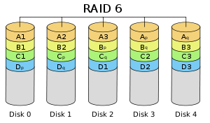
Raid Level 6

Striped set with dual distributed parity. Provides fault tolerance from two drive failures; array continues to operate with up to two failed drives. This makes larger RAID groups more practical, especially for high availability systems. This becomes increasingly important because large capacity drives lengthen the time needed to recover from the failure of a single drive. Single parity RAID levels are vulnerable to data loss until the failed drive is rebuilt: the larger the drive, the longer the rebuild will take. Dual parity gives time to rebuild the array without the data being at risk if a (single) additional drive fails before the rebuild is complete.

Raid Level 6
Advantages

  • RAID 6 is essentially an extension of RAID level 5 which allows for additional fault tolerance by using a second independent distributed parity scheme (dual parity).
  • Data is striped on a block level across a set of drives, just like in RAID 5, and a second set of parity is calculated and written across all the drives; RAID 6 provides for an extremely high data fault tolerance and can sustain multiple simultaneous drive failures
  • RAID 6 protects against multiple bad block failures while non-degraded
  • RAID 6 protects against a single bad block failure while operating in a degraded mode
  • Perfect solution for mission critical applications

Disadvantages

  • More complex controller design
  • Controller overhead to compute parity addresses is extremely high
  • Write performance can be brought on par with RAID Level 5 by using a custom ASIC for computing Reed-Solomon parity
  • Requires N+2 drives to implement because of dual parity scheme

Recommended Applications

  • File and Application servers
  • Database servers
  • Web and E-mail servers
  • Intranet servers
  • Excellent fault-tolerance with the lowest overhead

RAID 6 VS RAID 5

RAID 6
In complex arrays (12-24 drives), RAID 6 applications would be a preferred choice due to the fact that Serial ATA drives used in the arrays have a lower duty cycle and may be more likely to fail in 24/7 or business-critical applications.

Raid 5
In small arrays (4-12 drives), RAID 5 applications can quickly repair a failed drive and restore lost data-without taking down the array. It’s perhaps the most cost-effective, fault-tolerant data protection solution currently available for small storage devices.

Pro
Raid 6
Designed for tolerating two simultaneous HDD failures by storing two sets of distributed parities.

Raid 5

  • Simplified hardware implementation
  • A matured industry standard

Con
Raid 6

  • For RAID 6, one needs a more complex system with a method for encoding, as well as XOR calculations. For that, one really needs hardware acceleration, otherwise the performance suffers.
  • Uses 2 drives for parity

Raid 5

  • The risk of simultaneous drive failures grows in proportion to the drive array and can increase if customers purchase all of the disks in an enclosure at one time.
  • If the system finds a faulty sector on another drive during this degraded state (one drive down, spare drive being rebuilt), the RAID 5 system would be unable to restore the data onto the spare drive, resulting in data loss.

Recommended Configuration
Raid 6
Disk array consists of 12 disks or more

Raid 5
Disk array consists of 10 disks or less

Recommended Solutions

Raid 6

  • Desktop: EnhanceRAID T8
  • Rackmount: EnhanceRAID R14; UltraStor RS16

Raid 5

  • Desktop: EnhanceRAID T4HCR, T5,T8
  • Rackmount: EnhanceRAID R4,R6,R8; UltraStor RS8 or RS2080

Raid 6 Rebuild Software

Read More

Switching Storage Controllers w/o Reinstalling Windows

One of the trends in personal computing these days is the prevelance of more options for hard disks and RAID systems than have been available in the past. As a result, many people want to move towards one of these systems as an upgrade, but at the same time want to avoid the hassle of reinstalling Windows and all applications. This has been exceedingly difficult and in some cases even impossible do to. However, with this guide, you’ll be able to perform this task in most cases with most hardware configurations.

What You Can and Cannot Do With This Guide

This guide is applicable to the person who has Windows currently starting up from one hard disk/hard disk controller combination, and wants to start that same Windows installation up from a different hard disk/hard disk controller on the same computer. For instance, you may want to upgrade from a single-disk installation of Windows to a RAID installation, or from an IDE drive to a SCSI drive, or from an IDE drive to a native-mode SATA drive. In general, this guide will work for any situation where the mass storage controller that has to be used for Windows startup is going to change.

This guide is NOT for adding another drive or controller to an existing system when the Windows installation doesn’t move from it’s existing controller. That is a much easier task and can be done with standard driver installation and the Disk Management utility in Windows. This guide is NOT for moving a Windows installation to completely different hardware (like changing your motherboard). There are some procedures posted on the Internet for that already. The guide is NOT for moving a hard drive within a system where the disk controller that is being used either does not change or uses the same drivers as the old one, or where Windows already has built-in drivers for the new controller (like a standard IDE controller).

Windows and Mass Storage Controllers

Windows treats all mass storage controllers the same way. Whether it’s a standard IDE controller, SATA controller, SCSI controller, or RAID controller, Windows has to have a driver for it in order to use it. Once Windows has a driver installed for the controller, Windows can start up from a hard drive attached to that controller as long as the machine’s BIOS can use the controller as the boot device.

When installing Windows for the first time on a system, most of the time no concern need be given to the mass storage controller, because in the past, 90% of the time, the storage controller is a standard IDE controller which Windows already has drivers for on its installation CD. Windows will detect the standard IDE controller and use it’s own drivers for it, thus enabling Windows to start up from the IDE controller.

If Windows does not have a driver on its CD for your system, the Windows text-mode setup program tells you that Windows cannot find a mass storage controller in your system, and prompts you to insert a manufacturer-supplied driver disk. This is the method to install mass storage controller drivers for most SCSI, RAID, and now some SATA controllers. Windows reads the driver off the floppy disk, and uses that driver to start up after installation.

If any situation arises where Windows does not have a driver installed for the mass storage controller you’re starting up from, you will get a blue screen STOP error, usually with the error STOP 0x0000007B (INACCESSIBLE_BOOT_DEVICE). If you’ve ever tried to copy a Windows installation from one controller to another with one of the partition copy tools and then tried to start it up, this is probably what you got.

The key item in this procedure that makes it work is that the procedure loads drivers for a storage controller that Windows will start up on before moving Windows to that storage controller. Once Windows has seen the storage controller and has had drivers loaded for it, Windows can now use that storage controller as the startup controller.

Requirements to Proceed

To proceed with this procedure, you will need the following:

* The Windows installation that you want to move must be Windows 2000 Pro, 2000 Server, 2003 Server, or XP.
* The old hard drive controller is currently installed in the system, drivers for it are installed in Windows, and the hard drive holding the current Windows installation is attached to that controller, and Windows currently starts up in this configuration.
* You will need some type of tool to copy a partition from one drive to another if you will be moving the Windows installation to a different hard drive as well as a different controller. The recommended tools are: Norton Partition Magic, Norton Ghost, Acronis True Image, or BootIt Next Generation/Image for DOS. There are a few other products out there as well. Be aware that Partition Magic will only run on Windows 2000 Pro or Windows XP – it does not support copying partitions containing a server operating system. For copying server partitions, I recommend Norton Ghost.
* You need the ability to have both the old disk controller and the new disk controller installed in the machine at the same time. If you can’t do this for whatever reason, there is a work-around that will be addressed later in the guide.
* If you will be copying the startup Windows partition to a different drive, the disk controllers involved in the copy operation must support Extended INT13h extensions so that they can be seen by the partition copy software. (Most SCSI and RAID controllers, and all modern IDE/SATA controllers support this).
* You need drivers for the new disk controller already downloaded and decompressed (if required) on your C: drive.
* You need to prepare a DOS-mode startup media for the partition copy program you will be using. For Partition Magic, you can boot the Partition Magic CD. For Norton Ghost, you need to create a Ghost boot floppy. For Acronis True Image, you can boot the Acronis True Image CD. For BootIt Next Generation/Image for DOS, create a startup floppy.

Disclaimers

This procedure carries some risk. It is not possible to forsee all possible hardware combinations, and there may be some that this procedure doesn’t work on. There is a risk of losing your data, all the way from minor problems to loss of the entire hard drive. As with any procedure where data loss is a risk, having a current backup of your data is strongly advised. I can’t be responsible for data loss, and I don’t guarantee that this procedure will work in all situations, nor that it will work at all times.

Procedure

This procedure assumes you’re using a different hard disk as well as a different disk controller. If you’re changing the disk controller only, skip steps 13-18 and just move your hard drive to the new disk controller in place of those steps.

1. Backup all important data. Use a different hard drive other than the ones that will be used in this procedure, or backup to a network storage device or tape drive.
2. Shut down the system (power off).
3. Install the new disk controller in the system, but do not connect any drives to it.
4. Power on the system, go into the system BIOS.
5. Make sure in the boot order, that your original disk controller and hard drive are still set to be the boot device.
6. Save changes in the BIOS if necessary, and restart the system.
7. Allow your existing installation of Windows to start up.
8. Once Windows is started up and has reached the desktop, the Found New Hardware wizard should start, indicating that the system wants to install drivers for the new disk controller.
9. Install the drivers according to the manufacturer’s directions. Make sure you’re installing the correct driver. Many manufacturers provide a driver package that has drivers for several different, but similar products. Make sure you pick the driver for the exact disk controller that you have installed in the system.
10. When you’re done, Windows may ask you to restart. Do so now.
11. After the restart, check Windows device manager, make sure your new disk controller appears in the device list (under IDE ATA/ATAPI Controllers if it’s an IDE/SATA device, or under SCSI and RAID Controllers if it’s a SCSI card or RAID device). Make sure there is no yellow exclamation point or red X on the device. Double click it to make sure Windows says that the device is working properly.
12. Shut down the system (power off).
13. Attach your new hard drive(s) to the new disk controller.
14. If your new controller is a RAID controller and your intention is to create a new RAID array for your Windows installation, power on the system, go into the RAID BIOS Utility and create the RAID array on the new drives according to the manufacturer’s directions.
15. Power on the system and start up the DOS-mode partition copy utility that you have, either from CD or floppy.
16. You should now see the existing Windows partition on your old disk controller/hard disk, and a blank area on the new disk controller/hard disk/RAID array. Following the manufacturer’s directions for your partition copy utility, copy the partition from the old drive to the new drive/array.
17. Exit the partition copy utility and shut down the system (power off).
18. Remove the old hard drive from the old disk controller, but leave the controller installed.
19. Power on the system, go into the system BIOS. Make sure that in the boot order, the new disk controller is set as the startup device.
20. Save changes to the BIOS, and restart the system.
21. Windows will now start up on your new disk controller & hard drive.
22. Once started up and at the desktop, go into Device Manager.
(Note: steps 23-25 should not be done if the old disk controller will be hosting other drives, such as a second hard drive or CD/DVD).

23. Right-click and uninstall the old disk controller (under IDE ATA/ATAPI Controllers if it’s an IDE/SATA device, or under SCSI and RAID Controllers if it’s a SCSI card or RAID device).
24. Shut down the system (power off).
25. Remove the old disk controller from the system (or disable it in the system BIOS if it’s a motherboard-embedded device).

Congrats, your system is now starting up on a different disk controller.

Example

Earlier in the guide, I mentioned that you need to be able to install both the old and new disk controllers in the system for the procedure to work. There is a work-around if this isn’t possible. What you do in this case is use an intermediate disk controller, and perform the procedure twice. 😯

Let’s use an example for a typical scenario. Let’s suppose I have a motherboard with an Intel ICH7R south bridge (this south bridge chip is typically paired with the 975X north bridge chip). I currently have my Windows installation installed on a single 120GB SATA hard drive connected to the ICH7R, and the ICH7R is currently in native SATA (AHCI) mode. I want to move the existing Windows installation to a RAID-0 configuration, where the ICH7R is in RAID mode, using two new 150GB WD Raptors.

The problem with this move is that the ICH7R can be in SATA mode or RAID mode, but can’t be in both at the same time. Thus, we can’t have both the old controller and the new controller installed simultaneously. What we will do in this case is install an inexpensive SATA PCI card, like the Promise SATA300 TX2plus, move the Windows installation to that controller using the procedure above (1st pass), change the ICH7R to RAID mode, install the Raptors, create the RAID array, and then move the Windows installation from the Promise card to the RAID array using the procedure above again (2nd pass).

So, step-by-step:

1. Backup all important data. Use a different hard drive other than the ones that will be used in this procedure, or backup to a network storage device or tape drive.
2. Shut down the system (power off).
3. Install the Promise SATA300 TX2plus disk controller in any PCI slot, but do not connect any drives to it.
4. Power on the system, go into the system BIOS.
5. Make sure in the boot order, that the ICH7R disk controller and 120GB SATA drive are still set to be the boot device.
6. Save changes in the BIOS if necessary, and restart the system.
7. Allow the existing installation of Windows to start up.
8. Once Windows is started up and has reached the desktop, the Found New Hardware wizard should start, indicating that the system wants to install drivers for the Promise SATA300 TX2plus disk controller.
9. Install the drivers according to Promise’s directions. Make sure you’re installing the correct driver.
10. When you’re done, Windows asks you to restart. Do so now.
11. After the restart, check Windows device manager, make sure the Promise SATA300 TX2plus disk controller appears in the device list (under IDE ATA/ATAPI Controllers). Make sure there is no yellow exclamation point or red X on the device. Double click it to make sure Windows says that the device is working properly.
12. Shut down the system (power off).
13. Since the old connection to the ICH7R was SATA, and the Promise card also supports a single SATA drive, we don’t need another hard drive, nor do we need to copy the partition. Simply unplug the 120GB SATA drive from the ICH7R and reconnect it to the Promise SATA300 TX2plus.
14. Power on the system, go into the system BIOS. Make sure that in the boot order, the Promise SATA300 TX2plus disk controller is set as the startup device.
15. Save changes to the BIOS, and restart the system.
16. Windows will now start up on the Promise SATA300 TX2plus disk controller & 120GB SATA hard drive.
17. Once started up and at the desktop, go into Device Manager.
18. Right-click and uninstall the ICH7R driver (under IDE ATA/ATAPI Controllers – it will be listed as Intel 82801FR SATA Controller).
19. Restart the system.
20. Go into the system BIOS, change the ICH7R from SATA mode to RAID mode.
21. Allow the existing installation of Windows to start up.
22. Once Windows is started up and reached the desktop, the Found New Hardware wizard should start, indicating that the system wants to install drivers for the ICH7R in RAID mode.
23. Install the drivers according to Intel’s directions. Make sure you’re installing the correct driver.
24. When you’re done, Windows asks you to restart. Do so now.
25. After the restart, check Windows device manager, make sure the ICH7R RAID mode disk controller appears in the device list (under SCSI and RAID Controllers). Make sure there is no yellow exclamation point or red X on the device. Double click it to make sure Windows says that the device is working properly.
26. Shut down the system (power off).
27. Attach the two 150GB Raptors to the ICH7R disk controller using SATA cables.
28. Power on the system, go into the Intel Matrix Storage Manager RAID BIOS Utility (Ctrl-I).
29. Create a RAID-0 array using the two 150GB Raptors, making a 300GB virtual disk.
30. Restart the system and start up the DOS-mode partition copy utility that you have, either from CD or floppy.
31. You should now see the existing Windows partition on the Promise SATA300 TX2plus disk controller and 120GB SATA drive, and 300GB of space on the RAID array attached to the ICH7R. Following the manufacturer’s directions for your partition copy utility, copy the partition from the 120GB SATA drive to the 300GB RAID-0 array. You will either need to resize the partition afterwards to 300GB (Partition Magic) or define the size of the destination partition as 300GB before the copy (Ghost).
32. Exit the partition copy utility and shut down the system (power off).
33. Remove the 120GB hard drive from the Promise SATA300 TX2plus disk controller, but leave the controller installed.
34. Power on the system, go into the system BIOS. Make sure that in the boot order, the ICH7R/RAID array is set as the startup device.
35. Save changes to the BIOS, and restart the system.
36. Windows will now start up on the RAID-0 Raptors on the ICH7R.
37. Once started up and at the desktop, go into Device Manager.
38. Right-click and uninstall the Promise SATA300 TX2plus disk controller (under IDE ATA/ATAPI Controllers).
39. Shut down the system (power off).
40. Remove the Promise SATA300 TX2plus disk controller disk controller from the system.

Testing
I have tested this procedure using the following:

* An Intel D925XCV motherboard (925X north bridge, ICH6R south bridge)
* Windows 2000 Server
* A 120GB SATA Maxtor drive installed on the ICH6R in SATA/AHCI mode, holding the Windows 2000 Server installation.

1. I moved the Windows 2000 Server installation to an Adaptec 29160LP SCSI card with a 9 GB Seagate Cheetah SCSI drive.
2. I removed the Maxtor 120GB, changed the ICH6R to RAID mode, installed two 74GB WD Raptors, and created a 148GB RAID-0.
3. I then moved the Windows 2000 Server installation to the 148GB RAID-0.
All steps were successful. Norton Ghost was used as the partition copy utility.

References

My primary impetus for trying and deveoping this procedure is a Microsoft support KB article entitled Stop 0x0000007B error after moving the Windows XP system disk to another computer. This article says within it that installing a mass storage controller driver before moving the Windows installation will work. This is what I decided to test.

Some other Microsoft KB articles that deal with this, and other related issues are:

Moving a Windows Installation to Different Hardware
How to troubleshoot “Stop 0x0000007B” errors in Windows XP
How to perform an in-place upgrade (reinstallation) of Windows XP

Conclusion

I hope this procedure works for you and gives you additional options for your mass storage scenarios.

Read More