 IDE — This is simply an abbreviation for integrated-drive-electronics which is a physical attachment interface and is affiliated with the term ATA. It is often incorrectly used to describe a specific type of IDE/ATA interface known as Parallal-ATA (see PATA). See ATA.
EIDE — An extension of IDE, EIDE, or enhanced-IDE added to IDE support for larger drives (EIDE imposed a limit of 8.4GB, a vast improvement over the 528MB limit imposed by the original IDE design) as well as supporting faster throughput protocols. All modern hard drives whether labeled IDE or EIDE are in fact, EIDE devices.
ATA — An abbreviation for at attachment, (which fully expanded is advanced technology attachment). The ATA standard encompasses all aspects of interfacing with said devices: it defines physical, electrical, transport and command protocols for compliant devices. The ATA specification, introduced by the small form factor committee (SFF) is a 16bit interface which draws it’s roots from the ISA architecture.
Important: For the remainder of this guide, the term IDE will be used to define/describe the physical connections while the term ATA will be reserved for discussions revolving the electrical, transport and command protocols. Furthermore, EIDE and IDE drives will be grouped together under IDE and distinctions will be explicitly noted where required.
PATA — Parallel ATA, this refers to drives qualifying under the ATA specification (commonly this refers to non-SCSI drives) and make use of a 40-pin or 80-pin IDE connection. Also commonly (albeit vaguely/incorrectly referred to as “IDE”).
SATA — Serial ATA, this refers to drives qualifying under the ATA specification (again, essentially non-SCSI drives) and make use of a seven-pin (three ground, four signal) IDE connection. Native support for boot-time support of SATA drives is dependent on the chipset: if no support is available, boot-time drivers are required. SATA2 (aka SATA-II) is an extension of the serial ATA specification and allows for twice the throughput, connectors remain the same.
Important: For the remainder of this guide, the above terms/definitions PATA and SATA will be adhered to avoid ambiguity with the term “IDE”
PIO — Programmable I/O (input/output), this is a transfer/transport specification which falls under the larger definition of ATA. There are five different versions of PIO, Mode 0 though Mode 4 respectively. Original IDE (non-EIDE drives that is) only supported the first three modes of transfer (3.3MB/s, 5.2MB/s and 8.3MB/s respectively). The reason for this (the limited support) is because the interface was based on the ISA bus which had a limit of 8.3MB/s. Later EIDE drives added support for two more modes of transfer (11.1MB/s and 16.6MB/s respectively). Searching through Google you can find mention here and there of a last transfer specification, PIO Mode 5 which was supposed to support 22.2MB/s however it was not implemented due to the success of the DMA transfer specification. PIO is only supported on modern hardware as a fail-safe and/or troubleshooting transfer specification and should not be used in an active environment.
DMA — An acronym for direct memory access, this is often incorrectly taken to be synonymous with ATA when it is in fact a sub-component of the ATA specification (so it’s not too big a deal). There are six DMA transfer protocols: the first three are “Single-Word” and the latter are “Multi-Word” with the difference being the latter offering improved performance due to bursting operations. Single-Word modes 0-2 support transfer rates of 2.1MB/s, 4.2MB/s and 8.3MB/s respectively. Multi-Word Modes 0-2 support transfer rates of 4.2MB/s, 13.3MB/s and 16.7MB/s. On modern systems, Multi-Word Mode 2 is commonly used as the transfer specification for optical drives.
UDMA — An extension of DMA, ultra-DMA operates on the PCI bus (which, for consumer systems, provides 133MB/s of available bandwidth); one of the fundamental changes between UDMA and DMA is that, with UDMA, the device attempting to access memory negotiates with the memory-controller directly rather than via another controller card. The second fundamental change was that CRC was introduced to improve reliability. Strictly with respect to transfers, one can consider UDMA to be the “DDR-ed” version of DMA as commands were processed on both edges of the clock. UDMA supports seven (possibly eight) transfer modes. Mode 0 (16.7MB/s), Mode 1 (25.0MB/s), Mode 2 (33.3MB/s), Mode 3 (44.4MB/s), Mode 4 (66.7MB/s), Mode 5 (100.0MB/s), Mode 6 (133.0MB/s) and Mode 7 (150.0MB/s). Since I don’t have a SATA-II setup I can’t verify if SATA-II operates in Mode 8 (300.0MB/s) or not. Like DMA, UDMA is often incorrectly labeled as being synonymous with ATA however again, this is an insignificant error). All these advantages of UDMA require too much signal clarity to be supported by “DMA cables” (correctly called 40-pin IDE cables) and as such a grounding wire was added for each signal wire to improve signal quality (hence we have 80-pin IDE cables). A bit of searching suggests SATA-II will be encompassed under the ATA Mode 7 protocol.
Important: For the remainder of this guide, since DMA won’t be found on modern hard drives, any reference to “DMA” will actually be referring to UDMA.
SCSI — Small Computer System Interface, SCSI is a high performance specification which lost out (in the consumer market) to the ATA family of specifications due cost-effectiveness (or lack thereof). SCSI provides a host of advantages and features ranging from hot-swapping to native-command queuing as well as the advantage of “not having your entire computer freeze for a moment when one inserts an optical disc into the optical-drive”. SCSI is an extensively parallel interface (hence operations affecting optical drives do not interfere with those affecting hard drives and vice versa). SCSI devices (whether they be hard drives, optical drives, scanners etc) require termination (to maintain signal quality); furthermore there are many “icky” or painfully-annoying configuration operations required to prepare a SCSI system which is another reason it is not common in the consumer market. The SCSI aggregate transfer rates are:
- SCSI-1 (aka regular SCSI) — 8bit “Narrow” interface providing 5MB/s
- fast SCSI — 10MB/s on “Narrow”, 20MB/s on “Wide” or 16bit interface
- fast 20 SCSI (aka ultra SCSI) — 20MB/s on “Narrow”, 40MB/s on “Wide”
- fast 40 SCSI (aka ultra2 SCSI) — 40MB/s on “Narrow”, 80MB/s on “Wide”
- fast 80 SCSI (aka ultra160 SCSI) — 160MB/s on “Wide” interface
- fast 160 SCSI (aka ultra320 SCSI) — 320MB/s on “Wide” interface
SCSI connectors come in 50, 68 and 80 pin configurations; adaptors are available on the market for interfacing between these connectors. It is Important to note that looking at SCSI from the physical-layer, connections need to be done in “straight line”. What this means is that many SCSI cards come with thre connectors (two internal, one external) — you cannot use all three connectors simultaneously (if you did, the physical-layer would look like a “t” and thus parallelism would be seriously messed up). For advanced RAID configurations, SCSI is the only supported interface
Word — A term for two-bytes or 16-bits. In the context of Multi-Word DMA, this refers to the [burst] transfer of multiple words to/from the drive controller without the explicit command for those additional words being sent
Burst — An operation/transaction is said to be “bursted” or “in burst Mode” when the device being read provides more [sequential] data without explicitly being asked to do so. This is based on the principle that “if the controller wants data from location x, it’s highly likely that data from x+1, x+2, x+3 etc will also be desired”
Controller — Generically this refers to some form of chip-logic which allows a computer to interact with a given device. Controllers can be found built-into a motherboard (i.e., IDE/ATA controllers) or via add-in cards (i.e., SCSI controller). Some controllers provide additional features such as RAID.
CRC — Cyclic Redundancy Checking, this is a basic error checking routine whereby a mathematical calculation (binary polynomial division and remainder is used as the verification unit) to determine if data was corrupted during transmission.
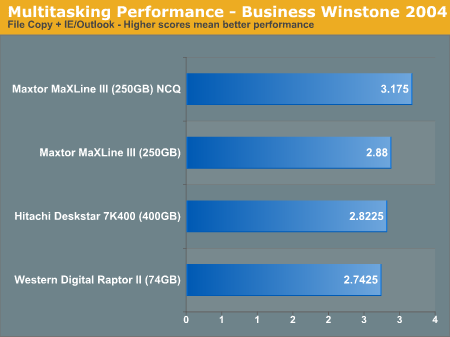
Native Command Queuing (NCQ) — Configurations (both drives and controllers require support) supporting NCQ attempts to queue together a series of instructions and execute them in the most efficient manner possible (efficiency is with respect to the physical layer). As a quick example, suppose data is required from “location” 1000, 55000 and 1005; a non-NCQ drive processes requests literally, 1000->55000->1005 but a NCQ configuration will process it as 1000->1005->55000. The difference is that the time it takes for read-write heads to move from location 1000 to 1005 is miniscule however the transition to/from 5500 is significant. A single queue of operations may not yield impressive performance gains however hard drives are required to execute millions of such transactions and those gains are cumulative
Partitioning and Formatting — Straight out of the box, a hard drive’s file system is “raw” which is unusable. In order to bring the drive to a useable state, it must first be partitioned and then those partitions need to be formatted. Partitioning refers to the process of subdividing the available space on a HDD into logical units (thus making c, d, e etc “drives”). Formatting refers to converting the file system from “raw” to format recognized by the operating system such as FAT, NTFS or EXT2
Cache — Hard drives are mechanical devices: no matter how much you improve the dynamics or increase the spindle speed, a mechanical transfer will always lose out (in terms of performance) to an electrical system. To alleviate/hide the slow nature of hard drives, they [the drives] are often equipped with a small amount of high-speed memory. When a request is received, the drive checks for a match in the cache before “manually” locating the data on the various platters: if there is a cache-hit (i.e., the data required is there) then the data can be immediately transferred thus eliminating seek times. Increasing the amount of cache available on the drive noticeably improves. Hard drives usually come with 2MB, 8MB or 16MB of cache. For some fancy RAID controllers, there is also cache memory present on the controller.
Spindle Speed aka Rotation Speed — Measured in revolutions-per-minute this is literally the mechanical rotation speed of the disk platters. The faster the rotation, the sooner the drive heads can be positions underneath the desired location. Modern drives feature anywhere from 3600rpm to 15,000rpm.
[Average] Access Time — A composite measure of the seek-time and rotational-latency, access time (measured in ms) is the sum total of the time it takes to move the disk head to the appropriate track on the platter (seek time) and the time it takes to move the appropriate sector (of the platter) underneath the drive head (rotational latency). Rotational latency can be reduced by increasing the spindle speed.


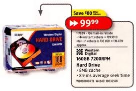

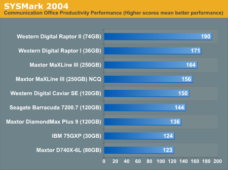
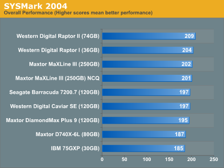
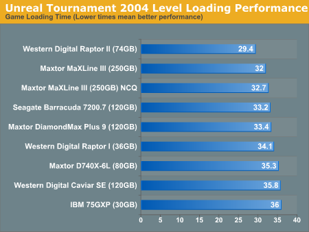



 1. TOSHIBA MK3265GSX 320GB 5400 RPM 8MB Cache 2.5″ SATA 3.0Gb/s Internal Notebook Hard Drive -Bare Drive
 2. WD SiliconEdge Blue SSC-D0128SC-2100 2.5″ 128GB SATA II MLC Internal Solid State Drive (SSD) – OEM
 3. WD SiliconEdge Blue SSC-D0064SC-2100 2.5″ 64GB SATA II MLC Internal Solid State Drive (SSD) – OEM
 4. HITACHI HDS721050CLA362 (0F10381) 500GB 7200 RPM 16MB Cache SATA 3.0Gb/s 3.5″ Internal Hard Drive -Bare Drive