Hard Disk Details(11)

Random Notes and Ideas For Data Recovery

    1. Drive goes to sleep, replace the board live
    2. Partitions start on Cylinder Boundaries
    3. Hard Drives have a Safe Mode
    4. You can fix LaCie problems with a Mac mounting them in the system
    5. Drives that you plug in that cause windows to Crash – Use Ubuntu to Read Files
    6. When problems with MFT then retry smaller blocks
    7. If drive parts are good then rewriting the SA area is the part that needs repairing
    8. SA Code can be replaced to do data destruction or encryption
    9. If you are thinking of a hard drive as 0’s 1’s then you are wrong. The equipment interprets signals to make the representation of 0s or 1s. Designers have taken into account the signal distortion and interface problems to make the work
    10. Remove a chip from the PCB and re-solder the chip onto a good board to fix specific problems with chips that are burned, cracked, etc
    11. Soft resets on SATA also need to do a hard reset the controller as it cannot be reset any other way like the bus is reset in a PCI or ATA
    12. ATA-3 Spec – hard drive read without retry was disabled and now is internal on the drive
    13. Seagate Drives use a serial interface of which you can find online. It will show you stats on the drive. If you see FFFF mask FFFF mask it is a head error
    14. If a drive is read with a standard read then it does not need to be read again but it might be good to use ECC to compare in a later pass
    15. Force the drive to use PIO mode instead of DMA/UDMA modes. Some hard drive failures cause the drive to fail reading UDMA but might still work in PIO
    16. Powers on good drive, while board is still in use move it to a new drive. Wrong defect tables and can be cleared
    17. If the platters are misaligned you can write data over the servo wedge and thereby destroying any chance that you can ever read the data
    18. As the thermal heat increases stability of the bits drop rapidly and with the addition of Areal density – degradation is much higher. There are fewer atoms in each bit to retain the bit orientation. Currently the drive will test for decay and if detected will automatically rewrite the data it detects
    19. Hard drives stored in heat for long term storage is extremely bad
    20. Adaptec ATA Raid 1200A Controller in combination with MHDD is great for recovery software.
    21. To determine if there is an HPA – Look at the LBA Maximum and if it is equal to Maximum Native LBA then there is no HPA
    22. Partitions created using standard disk partitioning tools, fdisk, Windows Disk Management, Partition Magic, will all be cylinder aligned. You only have to scan cylinder boundaries for partitions. Dynamic disks do not use partition tables, they use LDM which is at the end of the disk and needs to be done backwards. It uses one single partition occupying the entire disk minus one cylinder. When volumes are added or deleted the partition table is not updated. There are only 4 partitions possible with the standard Windows tools
    23. All partition table signatures end in 55 AA – if this is gone the OS will regard this as not existing. 80 is active 0B fat32 0F extended
    24. Everything in NTFS is a file – $boot
    25. Sector is the smallest addressable unit on the disk. You can read more than one sector but you cannot read less
    26. If doing a head replacement try straws for head stack replacements around the heads to keep them protected. Cut off a small piece of a drinking straw and place it over the head area of each and every head
    27. Even when the lower part of a head stack does not have heads they are still numbered.
    28. Increasing numbers of drive have no chance for parts replacement due to changes in the hardware
    29. Some drives store the lists in the NV Ram on the PCB. The table on one drive will not match the table on another drive and are unique. That might cause the same logical blocks to be mapped to different physical blocks on different hard drives. It is possible to have a swapped board cause a space on the hard drive to be overwritten due to the mapping problem.
Read More

Hard Disk Details(10)

Matching Serial Numbers on Hard Drives
This link is where I keep track of documentation on how each hard drive needs to be matched for a working donor drive.  I get this any where I can, use it if you can, and if you happen to find something out please let me know so I can add it to the collection!

NOTES:
Drives with the same model number can still have different numbers of heads, therefore the board is different. It is possible to identify the number of heads in a drive: Maxtor,Quantum, Seagate from the serial numbers:

REFIRBUSHED DRIVES
REFIRBUSHIED drives cannot be used as a donor drive. Head 0 is the bottom head and could be bad. And substandard parts are often installed. It is very difficult to match a refirb drive to a good drive with the same problems. This also makes it difficult to make repair a refirb drive.

QUANTUM
Quantum – the third number in the serial number shows the headsQuantum = HA code must match

SEAGATE
Seagate – the third SYMBOL in serial number represents the heads. Seagate’s sometimes have extra heads and when one is refurbished it is possible to turn off a bad head and turn on an alternate one and then the firmware number revision might change.

FUJITSU
Fujtsu needs the first xx-Xxxx to match

IBM and HITACHI DRIVES – Usually the same driveIBM MLC codes have to match

HITACHI
Hitachi ATMR 80gigs fails mostHitachi 3.5 – Firmware code needs to matchHitachi 2.5 – PCB rev has to match

WESTERN DIGITAL DRIVES
DCM codes for the (5th??? And) 6th numbers must match.No Western Digital drives with the letter R in the code. EB and BB models.Western Digital Drives EB and BB have the head stack affixed from the lid. Western Digital the sixth char in the model is the cache. U = 2meg V=8meg

SAMSUNG
Samsung the 4th Char in the alpha code on the label on the rear side needs to matchSamsung the 7th char in the model is the size of the buffer H=8megs

MAXTOR DRIVES
The second number of the serial number represents the number of heads Maxtor needs the 2nd and 3rd char to match:

Hi you all, this is the answer I received directly from Maxtor
Dear Mr. Robert,… here is the paragraph that deals with your model type (DiamondMax Plus 9):
For the following Maxtor hard drive models: Fireball 3, DiamondMax 16, DiamondMax Plus 8, DiamondMax Plus 9, Diamond Max 10 and all MaxLine products there is also a GTLA Number on the model (next to barcode on the bottom of the drive). Format 1Y222J2223322. 1, 2 and 3 stand for numbers, Y and J for letters. The numbers 1 and 3 as well as the letter Y need to be identical to be able to replace the PCB on these drives.  This number can be found on the large sticker on the top of the drive.

Unfortunately we cannot give you any more information than this. Any of your DiamondMax Plus 9 drives could possibly have a matching PCB, however it is most likely to be an older one as the drive in question is almost 3 years old.

Kind regards,
Gisela Schubert Technical Support
Maxtor Ireland Ltd.

copied from: http://forum.hddguru.com/howto-how-to-replace-maxtor-calypso-iii-board-vt5977.html

Serial Number on Hard Drive
The boot sector in the FAT32 partition

The boot sector in the FAT partition
The data contained in the boot sector after the OEM name string is referred to as the BIOS parameter block or BPB

Read More

Hard Disk Details(9)

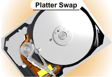
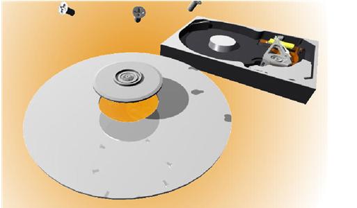
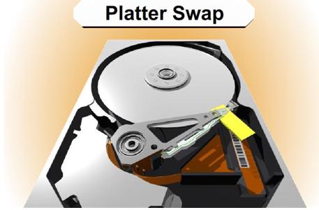
Slide 4500:  Doing a Platter Swap for a Single Platter

List of items needed:
The first step is to get a hard drive as close to identical as the bad drive you have that is a working drive. At the bottom of this paper you will find help about matching hard drives and serial numbers.
You need a clean area to work on with as little dust floating around as possible.
You will need about 1 hour to do this carefully
A screwdriver set with T3-T8.  These are my favorite http://www.wihatools.com/200seri/278serie.htm
Post-it Notes
Other tools depending on the drive
Anti-Static Gloves ($5 at the local store)
Patience

Just move the head as careful as you can to get it out of the way

NOTE:
This is a fairly simple task compared to a head swap. The hardest part is again getting the heads aligned and back on the platter correctly.
If you have a ramp on your drive it is fairly simple to get the head moved out of the way enough to get the platter in position.

Remove the platter from the good drive.

NOTE:
I usually will try to put a screwdriver in the shaft just to the edge of the center of the platter and turn the drive just enough to get the platter to slide on to the screw driver. I will do the same for the bad drive to move the platter to the good drive.

The platter will most likely never be used again so just get it out however you can without affecting the rest of the drive.

Again I use the Post-it notes in the shape of a V to get the heads back on the platter as I did in the head replacement.

Be very careful to keep the orientation in the same direction to so that the platter will be in the correct location when you put the platter back on the new drive.

Slide TBD: Doing a Platter Swap for a Multi-Platter

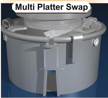
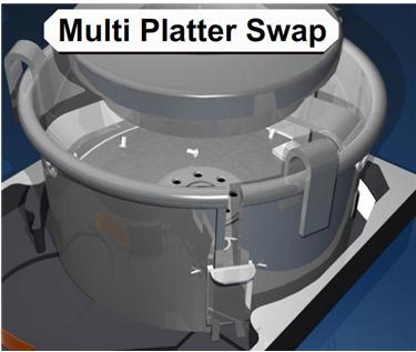
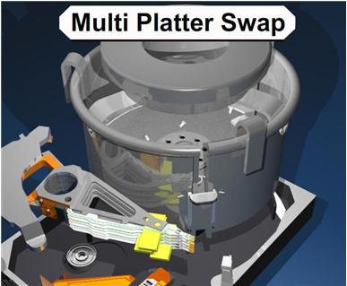
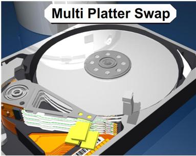
In order to do a Multi-Platter replacement you will need a special tool. If you have more than one platter and you take out the platters and any one of them turns at all, you will never get them aligned again or be able to read the data. This is because the data is written in a cylinder. Since the data is in a cylinder you must have the exact same alignment of the platters in order to move them to a new hard drive.

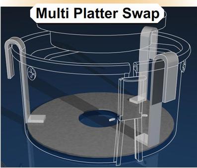
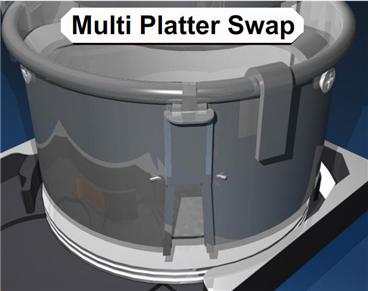
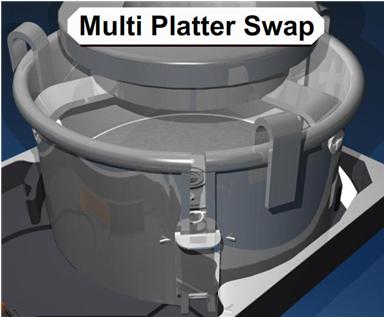
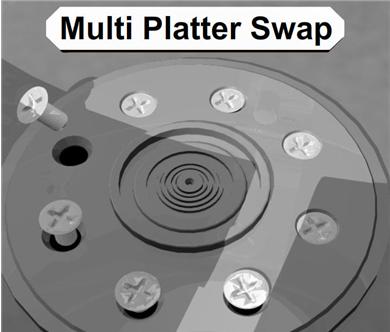
There is a special tool called a Platter Replacement Stand. You can get one at SalvationData.com  http://www.salvationdata.com for around $250 plus postage. It is a really heavy stand and weighs about 10 pounds.  The platter replacement tool is what you really need and it looks a lot like a coffee can with a slit in the side.  Once you have moved your heads out of the way, this can sits down around all the platters and you can push down on a piece of metal mounted in the slit to tighten it around the platters.  It also has a lid inside that sits on the top ring of the platters that will hold the screws and keep them from rolling around all over the platters.

The pressure from the “coffee can” will hold all the platters together; however you still have to be really careful about taking it out and turning it. It should go straight from one hard drive to the other as quickly as possible with as little movement as possible.

This is the best possible way to keep the drive platters lined up.

You will still reassemble the drive just like you do in a head stack replacement or a single platter replacement. The only difference is using this device to move the platters.

The plate inside the tool holds the screws so that they do not scratch the platter.

Realign the heads.

Read More

Hard Disk Details(8)

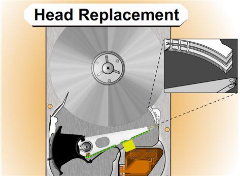
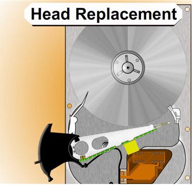
Slide 4259: Head Replacement Section
This is the only section from last year I kept and it is because this is directly related to fixing this click of death problem.
NOTE: If there is only one platter it might be easier to move the platter than to move the assembly. You have to make that choice.

List of items needed:
The first step is to get a hard drive as close to identical as the bad drive you have that is a working drive. At the bottom of this paper you will find help about matching hard drives and serial numbers.
You need a clean area to work on with as little dust floating around as possible.
You will need about 3 hours to do this carefully
A screwdriver set with T3-T8.  These are my favorite http://www.wihatools.com/200seri/278serie.htm
Post-it Notes
Other tools depending on the drive
Patience

Process for Head Replacement:
1.  You will need to disassemble the heads and other components from the drive to clear the room for the head and components.

2.    Disassemble the new hard drive, and carefully use folded paper to move the heads apart and to keep them apart as much as possible.

NOTE: If you are going to move the heads off of a drive platter you should always spin the motor in the direction away from the heads and the arm while you are moving the actuator arm to get the heads off. Move with care.

If you are storing the heads or going to put them down, you can try cutting sections of a drinking straw around the head itself. If the drive has a ramp it is very useful to help line up the heads to take them off and to put them back on.

*** There is often a screw under the assembly of the actuator arm that needs to be removed to move the heads.

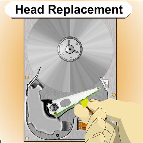
3.    Carefully lift the assembly out of the drive and move it to the bad drive and reassemble. It will take about two hours to assemble correctly if you take your time. Do everything you can to get the heads lined up again.

NOTE: It is helpful to fold a piece of post-it notes in a V shape and to make the V towards the platters and the heads on each side of the V.  You can get the paper to slide onto the platter and turn the platters with a screwdriver while you gently move the heads back into place.

You must get them lined up and review it before you turn the drive back on or the heads may slide into place and hit the edge of the platter ripping them off and scratching the platter.  It is good to practice with another drive you do not care about before doing this.

Read More

Hard Disk Details(7)

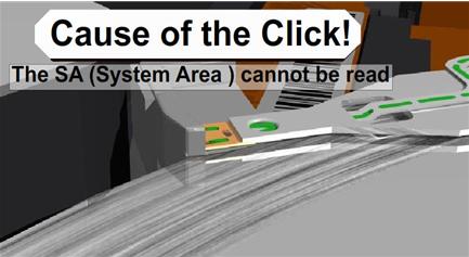
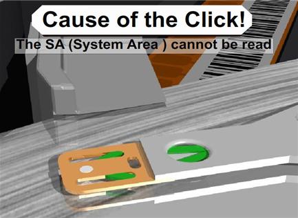
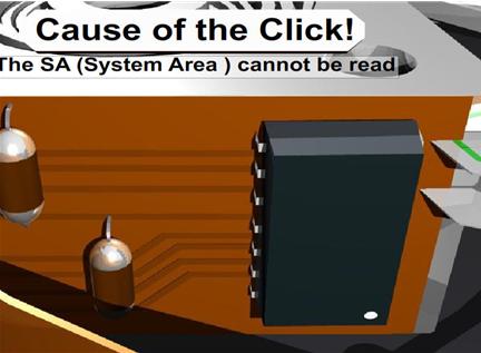
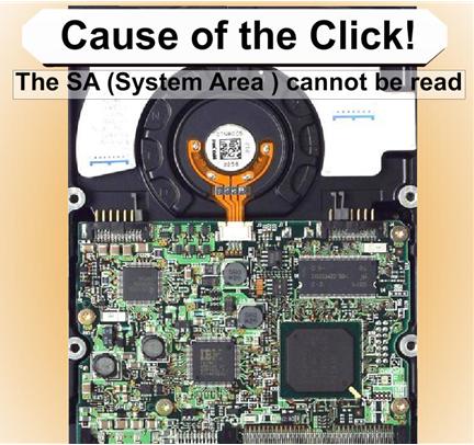
Slide 3791: The cause of the click is from four possible areas, all resulting in the SA not being able to be read.

1.    System Area of the drive cannot be read because the platter is scratched.

2.    The head itself has a problem and cannot read the SA area.

3.    Preamp on Actuator to the Head has gone bad and is not passing the correct signal to the electronics

4.   The firmware on the board is damaged and does not initialize. This is sometimes caused by static electricity walking across the carpet to install the drives, or there is a short on the board, and additionally I see where someone has allowed the board on the bottom of the drive to touch metal cause it to burn.

All will result in the same problem and will sound like the Click of Death. Recovery Software will not help you correct any of these until after you have repaired the drive and it is running again.

Correcting Problems
Now we move on to some of the things you can do about it on your own.  The click of death is a very difficult problem to solve and in some cases will not be able to be solved especially without some very high end and expensive equipment. But I will tell you what I have been able to fix without that equipment.

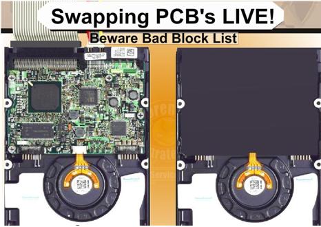
Slide 4009: Swapping the PCB (printed circuit board) Live to get around a SA area that cannot be read.

I have done this process several times successfully. It is not perfect but it is a possible chance you will have to recover your data. The first step is to get a hard drive as close to identical as the bad drive you have that is a working drive. At the bottom of this paper you will find help about matching hard drives and serial numbers. If the System Area is badly damaged or corrupt and for some reason the drive will not read the System Area you can attempt to do a live swap. What this means is that you can hook up the good drive, then you use software or windows and tell the drive to go to sleep.  This will cause the drive to spin down but will still be live and powered up and mounted.  Once the drive goes to sleep and the drive stops spinning you can unscrew the board, carefully so as not to let the screws roll around on the board, and disconnect the board and connect it to the bad drive. I suggest that once you do this, you go after the files you need very quickly. It’s possibly you will be able to make an image of the drive.  Keep in mind, that whatever bad blocks that the drive had assigned to the other drive will be bad here as well.  You could try to use some software to clear bad blocks before attempting this, however I don’t suggest it in most cases. That is because it is one more possible item that might cause failure. I would prefer to use the drive that was working and lose a few blocks. After you get what you can then you can attempt to make changes and go back for more data. This is a concept that works about 25% of the time.

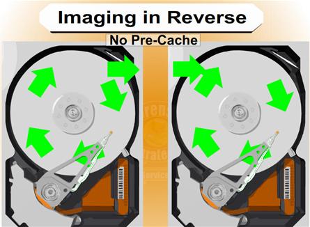
Slide 4199: Imaging in Reverse

In dealing with damaged hard drives, I have run into many problems with cache memory on the drive. The problems will often show up as timeouts or ECC failures as well. For example, I try to read from a drive with16 megs of ram for cache and receive errors but the drive is otherwise appears ok. If there is an error 16 megs away from the sector I am reading my drive will die. As of now there is no way to turn off this cache.  However, if you can image your drive backwards there is no cache. Memory on a drive only caches data forward. There are only three ways I know of to image a drive backwards. The first is free, and it is to use dd_rescue. dd_rescue has a special setting for imaging a drive backwards. There is also a special script for dd_rhelp to control dd_rescue for the purpose of data recovery. You can use this on Linux and it works on drives regardless of the operating system on the drive you are recovering from. Typically you will start at the MaxLBA number and work backwards down to 0 LBA. It works quite well and will work on a surprising number of drives that cannot be read any other way. Your other two choices are Media Tools Pro from RecoverSoft (http://www.recoversoft.com/) for Windows, which is about $400, or a piece of hardware which is extremely efficient at doing this type of recovery called Deepspar Disk Imager (http://www.deepspar.com/products-ds-disk-imager.html), which will cost between $3000 and $4000 depending on configuration. But you should contact each of these vendors for pricing, or use the free option!

Read More

Hard Disk Details(6)

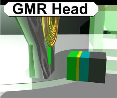
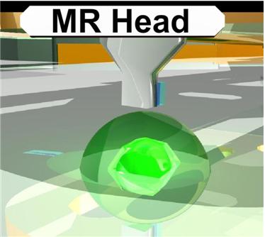
Slide 2840: The GMR (giant magnetoresistive) head is the current head used on most hard drives. This head uses high end physics I do not claim to understand. The only major difference is the way the head has been changed to read perpendicular. The GMR head has four layers, a sensing layer, a conducting layer, a pinned layer and an exchange layer.  It was discovered that if you took two magnetic layers and aligned them opposite each other with a soft layer between them that the magnetic force would align themselves in parallel. When a bit of data passes under the heads the electrons bounce around in the layers causing the pinned layer to spin.

For more info, read http://www.hitachigst.com/hdd/technolo/gmr/gmr.htm
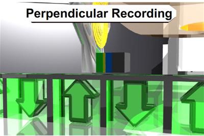
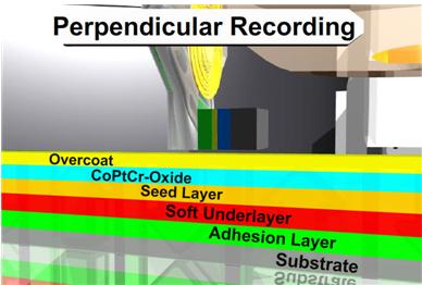
Slide 2865: Hard drives have switched to Perpendicular Recording.  I talked about the changes and previous versions last year and you can reference that speech for more info. The biggest change switching to perpendicular is that the data is written up and down instead of longitudinal. Because of this, changes had to be made to the platter so it would not interfere with reading and writing.

Slide 2885: The coatings have changed and  the substrate on the bottom (the platter itself) was the biggest change. Almost every platter has converted to a glass ceramic platter.  What this means to you in data recovery is that it is obvious when a scratch occurs. In most cases you will be able to see though the platter. Sometimes the rings that are created by the scratch are so smooth that they look like they are supposed to be there.  I assure you that they are not.  It should be silver from one edge to the other with no rings at all.  So if you see a ring, in most cases the game is over or your recovery just got a lot harder.

Slide 3000:  The data structure that is written to the sectors is important to understand if you are using any diagnostic software.  Many of them use common nomenclature to discuss the types of errors.

Common Error Codes and Diagnostic Info from Most High End Software:
BSY – drive busy
DRDY – Drive ready to accept commands
ERR – The Last Result was an Error
DREQ -exchange data with host
UNCR-Uncorrectable Error
WRFT – Write Fault
AMNF-Address Marker Not Found
IDNF- Sector ID Not Found
ABRT- Command Aborted
TONF – Track 0 not found

You will see the error codes here in almost all data recovery and diagnostic software.  This particular block of data (slide 3259) is one single sector. It contains a 512 byte block of data.  This is how on sector looks to every hard drive regardless of your operating system.

I could not possibly explain every error you will see, but I can give you the basics of the most common you will see doing diagnostics.

 IDNF is the Address not found. If the sector that holds this information is corrupt there is no way for the hard drive to locate this sector and it will return the result IDNF.

 AMNF is the Address Marker Not Found. This is similar to the IDNF but relates to the data. If there is an error and this marker is corrupt then the data for this sector cannot be located. The data in this area is 512 bytes of user data.

 ECC is that there is a problem reading from ECC and it does not match. ECC is used to check the integrity of the data being read. When the data is read the drive calculates the ECC and compares. If there is an error the drive will retry until it cannot get a correct result and then will return the UNC error.

 UNC will happen when the data is uncorrectable data error.

 ABRT is an abort error and it will discontinue trying to read that block

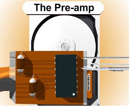
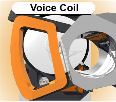
Slide 3559: The preamp is a chip that amplifies the signal coming from the heads of the drive. Since the data that is read coming from the heads is similar to a wave form from a speaker, the preamp will amplify it and send it on to the electronics for decoding. There are two types of preamps, one is soldered on, and the second is glued on.  It is often possible for a preamp to come loose due to heat expansion and not to have a good connection to the board. It is also possible for the preamp to fail. This is one of the causes of the click of death for the hard drive. It is often difficult to replace or fix this circuit and is more likely you can do a platter swap to a good drive, or replace the head stack assembly. The voice coil was mentioned in previous information at Defcon 14.

Click of Death and Hard Drives Safe Mode Notes
Errors cause the drive to constantly shutdown and recalibrate, this is a sound or movement that can usually be heard or seen and is known as the Click of Death for hard drives. If drive parts are good then rewriting the SA area is the part that needs repairing. The difficultly is in knowing if the rest of the parts are good. The SA can only be rewritten by a few devices. There are a few ways to get around this; one of the ways is a live PCB swap. Again the SA is not accessible over the interface without special tools.

Most hard drives have a specific recalibration routine they use to retry the SA area. Even though it cannot be read most drives will continue this routine.  A few drives will, after a certain number of times automatically power down.  The normal timing routine for this process is:
         Two head clicks
         power down
         two head clicks again
** Some drives will perform three head clicks before powering down.

Maxtor drives will test all heads from 0 to F; it must come out to level F, or stop the spindle. The problem of Quantum drives of all series (including last series — known as Maxtor D540X and D740X) can be detected by the specific sounds: after starting, there will be two loud clicks, then drive’s motor will increase its speed, and there will be 4 more clicks, after which the drive will become “ready”. For Western Digital a dead preamplifier is also detected by the specific sounds: after two loud clicks the drive will stop the spindle. If you have a clicking Maxtor then heads malfunctioning is characterized with a continuous clicking for over 30 seconds. Samsung drives with a dead preamplifier also click two times and then stop the spindle; however, for Samsung drives it can also mean problems with reading of the critical modules of the system area.

Hard Drives Safe Mode
Can be done by setting jumpers in case a module is damaged or some drives can detect it and go into safe mode itself. In safe mode the drive bypasses its own firmware and is waiting for firmware to be uploaded to ram. The RAM code is called the loader and will start the drive operations. It is possible for the hard drive to go into safe mode all by itself if it detects a problem. You will never know this is happening on purpose. Some software like MHDD might be able to tell you if your drive is in safe mode. You will never be able to recover data until this problem is solved and it is not running in safe mode. When it is running in safe mode it will sound like the Click of Death on most hard drives.
Diagnostic software called MHDD or Victoria
http://hddguru.com/content/en/software/2005.10.02-MHDD/

MHDD Software commands and functions:
Erase Waits:- It is better to use this for Drive Repair but it is data destructive
HPA :- Host Protected Area Functions
REMAP: – Try to recover bad sectors
Standby: – turn the motor off
PWD: – User Password INFO
Dispwd: – disable the password
Fdisk: can make one full size fat 32 drive

Read More

Hard Disk Details(5)

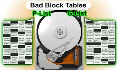
Slide 2221: When the drive is manufactured it is known that there is going to be errors in every drive.  Drives use ECC to correct most errors and if ECC can correct the error then the sector is never marked as bad.  If it is marked as bad, the drive puts the data in a bad block list. Most people know that their hard drive has a bad block table. What most people do not know is that their drive has TWO bad block tables.
1.    P-List (Primary Defects List – manufacture defect info that does not change)
2.    G-List (Grown Defects Lists – sector relocation table)

The G-List is where the bad blocks that your drive has on a daily basis are stored. Since the P-List is done at manufacturing time that list is never suppose to change. There is a very important reason to know about both lists in a low level recovery which I will explain when we get to the repair section. There are certain utilities that can read, delete, merge and change this data.

ECC Notes and Issues

ECC structured redundancy up to 200 bits of 256/512 in a sector-CRC–Scrambled Bits- RLL adds bits to cause pulses and Parity When data is written to the drive it is encoded. The actual data itself is never written, only the interpretation of the data. If you are thinking that a drive contains 0’s and 1’s then you are thinking about it incorrectly. The data is more like a wave form being written to the drive. It has to be interpreted back on its way out before it becomes a 0 or a 1. Before the data is written the data is randomized. This eliminates patterns that might be the same so that ECC is not confused. It is difficult to do pattern detection on a pattern that appears over and over. EMI can be reduced and have less effect on the bit storage and the timing controls.

The drive tries several different ways to re-read the data before giving up, most of them using ECC. It is possible for ECC to improperly correct data under certain circumstances if the data occurs in a certain order. ECC read commands use ODD numbering of at least 3 so as not to cause a 50/50 chance in the selection of 2.

Read ignoring ECC is an LBA 28 command “Read Long” and it was disabled in 48 bits as it was determined to be obsolete in drives over 137 gigs. No Read Ignore ECC is available after 137 gigs. Standard attempts are tried and usually are 10 tries in most hard drives. Reading a drive ignoring ECC can cause possible corruption in the data, but sometimes it is the only way to get the data in those sectors if there is a problem with the PCB or the ECC cannot read the data correctly.

If the Sector is determined to be unreadable by the ECC encoder then the sector is retried again. Reed Solomon in conjunction with sector rereads is expecting to fix data errors for the ECC. Parity bits are stripped off.

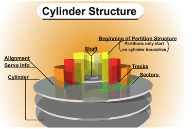
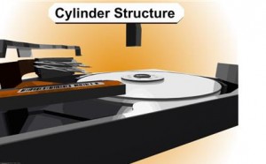
Slide 2422: The cylinder structure is extremely important because there are people believe they can just take the platters out and move them to a new drive. This is true you can do this, but you have to move all platters simultaneously. The reason is because data is written in a cylinder.  Most people have heard the term cylinder in reference to their hard drive, but they have no idea what that means. Writing in a cylinder means that data is written in parallel due to the fact the heads are always moving together in the same stack.  To make it more efficient data is written on the top of a platter and the bottom of the platter and the next platters and so on, at the same time.  Your data is NOT written on the top of one platter and when that gets full then written to the next platter. It is written across all the platters at the same time, making a cylinder of your data.

Most data recovery software will scan an entire hard drive and then display a list of files and directory trees you can recover from. However, if there is a lot of damage to the drive, the scanning may never finish or it might die/kill it in the process. If you have smart software and you can figure out where your partitions start and where the MFT or FAT tables might be, you stand a better chance of getting the data you are looking for.  If a standard utility was used to create the partition then the partition structure will begin on a cylinder boundary. Again, your partition will begin on a Cylinder Boundary. Software like Byteback (www.byteback.org) RecoverSoft Media Tools Pro (www.recoversoft.com), and Runtimes Disk Explorer (www.runtime.org) are smart enough to know the data exists on the cylinder boundary and will quickly check without you have to scan the whole hard drive and possibly saving your drive from disaster during the scan. There certainly are times that scanning will be required but it is best if you can avoid it except in an imaging process.
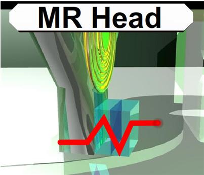
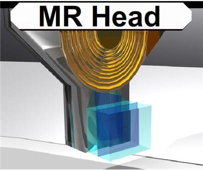
Slide 2585: The MR (magnetoresistive) head of the hard drive you can think of as the head of the 90’s. If you remember how reliable the drives were before 2000 it is mostly because of this head and the density of the platters.  This head was used on drives mostly before we crossed the 10-20 gig barriers. The MR head could determine if a bit passed under it.  When data passed parallel to the head, the head could detect the “MR Effect” due to movement of electrons causing the magnetic field to rotate positive and negative values.

Read More

Hard Disk Details(4)

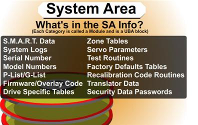
Slide 1781: What is in the System Area Info. Each category is called a Module and is a UBA block.

1.    Smart Data
2.    System Logs
3.    Serial Number
4.    Model Numbers
5.    P-List (Primary Defects List – i.e.: manufacture defect info that does not change)
6.    G-List (Grown Defects Lists – sector relocation table)
7.    Program Overlays – Firmware, Executable Code, or updates
8.    Specific Tables like RRO – (recalibrate repeatable run-out and head offsets)
9.    Zone Tables
10. Servo Parameters
11. Test Routines
12. Factory Defaults Tables
13. Recalibration Code Routines
14. Translator Data
a.    Converts Logical and Physical Address to locations on the drive
b.    Heads and Track Skewing Info
15. Security Data Passwords for drive – possible encrypted info.

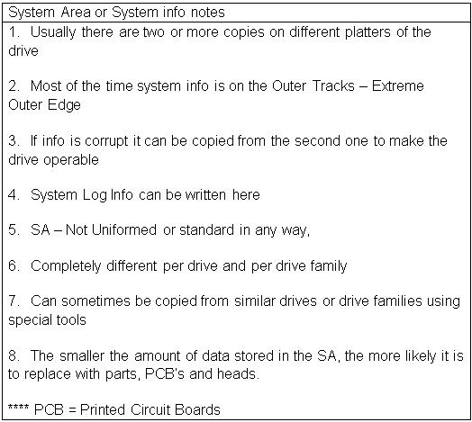
System Area or System info notes
1.    Usually there are two or more copies on different platters of the drive
2.    Most of the time system info is on the Outer Tracks – Extreme Outer Edge
3.    If info is corrupt it can be copied from the second one to make the drive operable
4.    System Log Info can be written here
5.    SA – Not Uniformed or standard in any way,
6.    Completely different per drive and per drive family
7.    Can sometimes be copied from similar drives or drive families using special tools
8.    The smaller the amount of data stored in the SA, the more likely it is to replace with parts, PCB’s and heads.
**** PCB = Printed Circuit Boards

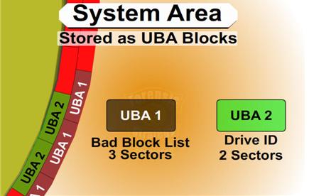
Slide 1816: The System Area is made of UBA Modules (Utility Block Addressing) which are sector blocks logically grouped together that contain a specific MODULE.  Each UBA block might be different per a drive manufacturer. The UBA # might be Smart Data on one drive and a different type of data on another drive. The UBA area is inaccessible over the standard interface. Most of the commands to talk to the UBA modules are vendor specific and which is generally not made publically available. There are certain pieces of hardware that can be used to communicate with this area such as the PC3000.

For example: In the UBA 1 Area it could be a Bad Block List.  As larger drives have been created there has been a need for larger bad block areas.  So this might be expanded from two sectors in a previous drive to three sectors in a newer drive. But the firmware for the drive can still refer to each of them as UBA 1 and does not have to have any changes made to the code in the firmware regardless of the size change.

Read More

Hard Disk Details (3)

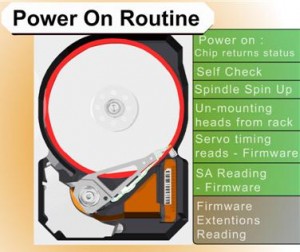
Slide 1289: The first thing a hard drive will do after it receives power is check for a return status from it’s chips to make sure the electronics are functioning. Then the drive will begin the self-check of its parts and wait for a return status. If both status checks are returned then the drive continues on to the next step and spin up the spindle.

Slide1389: The drive begins to spin the spindle or as you would see, the platters begin to revolve.  When the platters begin to revolve the air flow around the platter creates a force that is called an air bearing.  This air bearing will fling off debris on the platters such as any dust particles or metal fragments from the standard operation of the drive. This air bearing also causes the plastic locking arm mechanism to move out of the way as soon as there is enough air flow for the head to float. Without that airflow the arm is locked in place and will not move over the platter. This is a way to protect the platter from the head touching the platter and causing physical damage. The opposite is true during a power down. When power is cut to the drive, during the last revolutions of the motor, it generates enough power to move the head back to it park position.  Because of this, as you can imagine,  if you get enough power on and power off cycles in a row it is possible for the head to be stuck in the center of the platter and never to be parked correctly causing several types of damage. In certain 80 gig laptop 2.5″ inch drives it is common for the head to be stuck to the center of the platter, never having parked and keeping the platters from spinning. In most cases there is very little damage if the drive is opened and manually turned slow enough not to damage the head, and the data can be recovered, obviously never using this drive again.

Slide 1483: At this point, if the all has proceeded correctly the air bearing will allow the head to float over the platter allowing it to move freely without scratching the surface of the platter.

Slide 1545: At this point, if the head is reading the Servo Timing info from the platter and relaying it to the circuitry so the controller knows the geographic information for the placement of data.  (See previous speech at Defcon 14 for discussion about Voice Coil and stepping motors to understand the servo info).

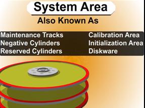
Slide 1679: At this point the head moves to the System Area (SA) of the platters and reads the content that it requires as well as any additional firmware and overlays.
Most of the time, the system area is on the outer tracks – the extreme outer edge. This is chosen by the manufacturer but is most common on the outside on 3.5 and is sometimes written to the inside tracks on a 2.5″ inch drive.

System Area Information Common Names

 1.      System Area
 2.      Maintenance Tracks
 3.      Negative Cylinders
 4.      Reserved Cylinders
 5.      Calibration Area
 6.      Initialization Area
 7.      Diskware

Read More

Hard Disk Details (2)

The hard drive knows nothing about your files and is not aware in any way of the content. That is the job of the Operating System (OS from here on). When the OS asks for a file, the OS will request a logical block from the drive; the drive will translate that to the physical location in CHS. An example is that it might request data from Cylinder 2500 at head 2 located on sector 234. The drive has many spare sectors and sometimes spare tracks to be used to compensate for errors and relocation of data. NOTE: Look at $BadClus on a NTFS File system for what the OS thinks is bad.

In a previous speech here at Defcon 14, I gave the basic inner workings of a hard drive and several ways you can repair it. I am sure that you can get that previous speech on DVD, find it on the web, or on www.myharddrivedied.com and it will give you a large amount of info that I am not going to discuss here today.  Additionally, there is a whitepaper on the CD that includes more data and notes about repairing a hard drive.

Since my last speech one of the most common questions I get everyday is “What is that clicking noise? How do I fix it?” This is not a simple problem by any means.  So my goal today is to give you more insight into the inner workings your hard drive and explain how this problem occurs and what you might be able to do to fix it.

Slide 1208: In this speech we are looking at the platter assembly where the heads are located, through the area of the preamp and the IC Logic Board down to the PCB.  This is the area that affects what is causing the clicking noise that you hear.  I am now going to explain how each of these things works and walk you through the drive functions.

Part of what causes this clicking problem is related to the power on routine functions.

The boot sequence of a drive is as follows:
1.      Power on chip returns status
2.      Self check
3.      Spindle spin up
4.      Un-mounting heads from rack
5.      Servo timing reads – firmware
6.      SA reading – firmware
7.      Firmware extensions reading
8.      Error – read SA from other secondary copies

Read More