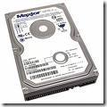
What is ATA/IDE?

ATA IDE Hard DriveWhat is ATA/IDE?
Integrated Drive Electronics
(IDE) is a generic term applied to any drive with an integrated (built-in) disk controller. The first drives with integrated controller were Hardcards. In the IDE architecture, the disk controller is integrated into the drive. This combination drive/controller assembly usually plugs into an interface on the motherboard or an interface card plugged into an empty bus slot. The ATA Specification is simply a set of rules or guidelines that an IDE drive should conform to.

Data transfer modes
PIO-Modes

PIO stands for Programmed Input/Output and was the standard way of using ATA devices but it has become less popular, in favor of the new DMA modes. There are five different PIO modes, each have different transfer rates. The higher the mode number the higher the transfer rate. All PIO modes use the CPU to transfer data which makes this method unsuitable for multitasking environments. Which brings us to the transfer mode used today: DMA.

DMA modes

DMA stands for Direct Memory Access and is the term used when a peripheral device transfers data directly to or from memory, without the use of the CPU. Today DMA is the only feasible way to transfer data from the hard drive to memory as most of todays operating systems use multitasking and can better use the CPU for other tasks. The first DMA modes were not adopted by the popular OS’s of the time, but when Ultra DMA mode entered the scene it quickly became commonplace. The main difference between Ultra DMA and the older singleword and multiword transfers was that Ultra DMA mode clocks the data twice per clock cycle thereby doubling the bandwidth. The most favored today is Ultra DMA mode 2, aka UltraDMA/33.

Standards
ATA-1

To eliminate some major compatibility problems with the early ATA/IDE drives the ATA-1 specification was defined as an ANSI standard in 1994. Previously the most common problem showed up when drives of different manufacturers were placed as master and slave on the same channel.
The original ATA/IDE standard defines the following features and transfer modes:
It supports one or two harddrives on the same bus. One is configured as master and the other as slave.

ATA-2

The ATA-1 standard defined what the interface was capable of a decade ago, and there was a need for faster transfer rates and enhanced features. In 1996 the ATA-2 standard was defined as an ANSI standard that is backward compatible with the older ATA-1.
– Faster PIO modes: 3 and 4.
– Faster DMA modes: 1 and 2
– “Identify Drive” command allows software to query the drive for it’s geometry and characteristics (Plug ‘n’ Play).
Several manufacturers marketed drives based on ATA-2 under different names like “Fast-ATA”, “Fast-ATA-2” and “Enhanced IDE”, which are all marketing terms and not real standards.

ATA-3

In 1997 this ANSI standard was defined and can be viewed as a minor revision to ATA-2 and includes improves the reliability of the faster transfer modes introduced with ATA-2. Also added was the open standard for monitoring disk drive health, SMART

ATA/ATAPI-4

This revision adds some significant and long-awaited features:
– ATAPI (AT Attachment Packet Interface) for devices that require commands not available in the standard ATA standard like CD-ROMs and CD-R.
– Removable Media (Zip drive).
– Overlapped feature set allows devices that require extended time to perform a bus release so that other devices on the bus may be used.
– Ultra DMA data transfer protocol, aka Ultra ATA, which clocks data twice per clock cycle by using both the negative and positive transition.
– Defines an 80 conductor cable to be used for Ultra ATA devices, it is not mandatory however.

ATA/ATAPI-5

Adds Ultra DMA mode 4 or Ultra DMA/66, the 80 conductor cable is now mandatory to maintain signal integrity.

ATA/ATAPI-6

Not finalized yet. It will definately add Ultra DMA mode 5 or Ultra DMA/100 as it is already integrated in drives manufacturered today. Discussions are being held concerning noise reduction which can be found in drives shipping today as well.

Cabling for ATA

It’s easy to describe the different cable types used by the ATA interface today because there really is only one standard. And that is a 40/80 PIN flat cable with 3 IDC connectors. You can attach up to two units on the cable, one master and one slave. The 80 pin cable is for use with Ultra DMA devices but the 40 pin cable can be used with newer Ultra DMA devices but no faster modes than Ultra DMA/33 are available in that case.
In latter years a new cable has emerged, a 44 pin flat cable which is mostly used for 2.5″ internal harddrives. The 4 extra pins are used for supplying power to the drive.

Future for ATA

In order for the ATA interface to cope with the increased data clock rate in the future, a proper terminator has to be applied to prevent “ringing” in the cable. This is not easily solved while achieving backward compatibility and will require cooperation between the major hardware manufacturers to make it work. Perhaps a solution is around the corner as there is a draft for a FireWire ATA interface.

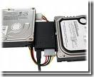
Read More

An Old IDE Drive May Not Work With A New IDE Drive?

Why is it that an Old IDE drive may not work with a New IDE drive?

The reason is the fact that many hard drive manufacturers were already making and selling drives before the IDE standard was clearly defined. Older IDE drives have problems functioning in dual-drive configurations. This scenario is more prevalent when the hard disk drives are from different manufacturers; in some cases, two drives may not function together at all. However, in rare circumstances even new drives will not work together.
Solution:

  • Separate the drives and have them on their own cable. Designate one drive as the Primary Master and the other as the Secondary Master.
  • Try not to jumper the drives as Cable Select. Have the drives jumpered as a “Master” drive.
Read More

IDE/EIDE Interface Part II

IDE/EIDE Interface This is a general description of the most frequently asked questions about the IDE/EIDE Interface. This information is meant only to address basic troubleshooting of IDE/EIDE compatibility issues, and is not meant to be an in-depth discussion of all possible error issues. Our purpose is to aid you in solving basic IDE/EIDE difficulties that may arise.

Issues Covered:

  • IDE/EIDE Definitions
  • Compatibility Issues

11.Why is the 20th hole plugged on the Ribbon Connector?

It is a means of preventing the cable from being installed (plugged in) upside down. Users that inadvertently plug a cable in backwards can cause damage to both the hard drive and the motherboards interface. If your system does not have the corresponding missing pin, you may remove this plug by “teasing it out” with a straight pin.

12. Does the IDE interface cable influence data integrity, signal noise issues and drive recognition?

The answer is Yes! The ATA standard specifies that an IDE Interface cable should be no longer than 18 inches. The standard cable used today conforms to the ATA specifications. However, 40 pin interface cables do not always filter out noise when used with the Ultra DMA 33, 66, 100 and even 133 hard drives of today. Another option for reduction of cable noise would be to use an 40-pin 80-wire interface cable. These cables provide better grounding to maximize signal integrity.

13. Will adding an EIDE Interface increase disk performance?

Although most, if not all computers manufactured today have the fastest interface available, the answer really depends on the hard disk drive. Unless you’re working with legacy equipment, a new interface may not give you a performance increase. As an example, upgrading an ISA controller to a PCI controller would be the biggest improvement a user could make.

14. Why is the hard disk drive NOT as fast as advertised?

Advertised transfer rates are based on the fastest speed at which the drive can send data across the ribbon cable from the drive buffer, with the transfer stopping temporarily every time the buffer re-fills. This process continues until a command is complete. Data transfer rates will differ between system configurations, as a drive is not the single component that decides transfer rates. The one thing that designers have control of is the speed at which data transmits across the data ribbon cable from the drive’s buffer, but not how your other components interact with the drive.

15. Why is it that an old IDE drive may not work with a New IDE drive?

The reason is the fact that many hard drive manufacturers were already making and selling drives before the IDE standard was clearly defined. While this is now, for the most part, relegated to very old IDE drives that have problems functioning in dual-drive configurations. This scenario was more prevalent when the hard disk drives are from different manufacturers, however, in some cases, two drives may not function together at all. Even today though, in rare circumstances even new drives will not work together.

16. Why is my new IDE drive not recognized as a slave or a master?

Configuring IDE drives can be simple, as is the case with most single-drive installations, or troublesome, especially when mixing drives from different manufacturers on a single cable. Most IDE drives must be configured in one of the following ways:

  1. Single-drive (master)
  2. Master in a dual-drive system
  3. Slave in a dual-drive system

Because each IDE drive has its own controller, one drive must be jumped as a master and the other as the slave. There are no functional differences between the two, except that the drive that’s specified as the slave will assert the DASP (Drive Active/Slave Present) signal after a system reset to inform the master that a slave drive is present in the system. Daisy-chained hard disk drives that do not have their jumpers set correctly will not function. You should contact the disk drive manufacturer if you are unsure of proper jumper settings.

17. Two hard disk drives will not function even after verifying jumper settings. What could be wrong?

There may be a compatibility problem between the two drives. Use the following steps to verify the function of each drive:

  1. Test each drive by itself, making sure that each drive has been jumpered correctly. If both drives work by themselves, you may conclude that there is a compatibility problem.
  2. Try “swapping” (switching) the drive’s position, what was the master will be changed to a slave and the slave will become the master.
  3. Most motherboards have two IDE bus connectors. Place one drive on each IDE bus and test the system.

18. Why does an IDE CD-ROM and Tape Backup not work when attached to the Interface?

On  occasion, attaching an IDE CD-ROM or tape backup drive to a bus that supports an IDE drive, can slow down and even compromise the drive’s data integrity. Although this is extremely rare today, make sure that your systems motherboard has an Enhanced IDE interface that is ATAPI compliant. If it is not, you can purchase and add-in card that has this interface, and they usually come with a secondary IDE interface built on the same card.

19. Even after switching roles, my hard drives still will not work. What else can I do?

First, see questions 16 and 17 above. We recommend that you separate the hard drives and connect them to the different interface ports (IDE buses) of the system. If the system does NOT have a Secondary IDE interface, we recommend that you install an EIDE interface card. By doing so, each of your drives would be able to communicate individually with the system. Enhanced EIDE cards also can add BIOS LBA support and enhanced performance for the drives.

20. Why are 80-wire, 40-pin ribbon cables required for certain hard drive configurations?

40-conductor cables support only up to 33MB/sec transfers (and should only be used for up to 16MB/sec or less in our opinion), while 80-conductor cables support up to 100MB/sec. Thus you can always replace a 40-conductor cable with an 80-conductor cable, but not the other way around without seriously hurting transfer speeds, and quite possibly damaging one or more of your systems components.

Read More