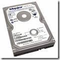
 What is ATA/IDE?
Integrated Drive Electronics (IDE) is a generic term applied to any drive with an integrated (built-in) disk controller. The first drives with integrated controller were Hardcards. In the IDE architecture, the disk controller is integrated into the drive. This combination drive/controller assembly usually plugs into an interface on the motherboard or an interface card plugged into an empty bus slot. The ATA Specification is simply a set of rules or guidelines that an IDE drive should conform to.
Data transfer modes
PIO-Modes
PIO stands for Programmed Input/Output and was the standard way of using ATA devices but it has become less popular, in favor of the new DMA modes. There are five different PIO modes, each have different transfer rates. The higher the mode number the higher the transfer rate. All PIO modes use the CPU to transfer data which makes this method unsuitable for multitasking environments. Which brings us to the transfer mode used today: DMA.
DMA modes
DMA stands for Direct Memory Access and is the term used when a peripheral device transfers data directly to or from memory, without the use of the CPU. Today DMA is the only feasible way to transfer data from the hard drive to memory as most of todays operating systems use multitasking and can better use the CPU for other tasks. The first DMA modes were not adopted by the popular OS’s of the time, but when Ultra DMA mode entered the scene it quickly became commonplace. The main difference between Ultra DMA and the older singleword and multiword transfers was that Ultra DMA mode clocks the data twice per clock cycle thereby doubling the bandwidth. The most favored today is Ultra DMA mode 2, aka UltraDMA/33.
Standards
ATA-1
To eliminate some major compatibility problems with the early ATA/IDE drives the ATA-1 specification was defined as an ANSI standard in 1994. Previously the most common problem showed up when drives of different manufacturers were placed as master and slave on the same channel.
The original ATA/IDE standard defines the following features and transfer modes:
It supports one or two harddrives on the same bus. One is configured as master and the other as slave.
ATA-2
The ATA-1 standard defined what the interface was capable of a decade ago, and there was a need for faster transfer rates and enhanced features. In 1996 the ATA-2 standard was defined as an ANSI standard that is backward compatible with the older ATA-1.
– Faster PIO modes: 3 and 4.
– Faster DMA modes: 1 and 2
– “Identify Drive” command allows software to query the drive for it’s geometry and characteristics (Plug ‘n’ Play).
Several manufacturers marketed drives based on ATA-2 under different names like “Fast-ATA”, “Fast-ATA-2” and “Enhanced IDE”, which are all marketing terms and not real standards.
ATA-3
In 1997 this ANSI standard was defined and can be viewed as a minor revision to ATA-2 and includes improves the reliability of the faster transfer modes introduced with ATA-2. Also added was the open standard for monitoring disk drive health, SMART
ATA/ATAPI-4
This revision adds some significant and long-awaited features:
– ATAPI (AT Attachment Packet Interface) for devices that require commands not available in the standard ATA standard like CD-ROMs and CD-R.
– Removable Media (Zip drive).
– Overlapped feature set allows devices that require extended time to perform a bus release so that other devices on the bus may be used.
– Ultra DMA data transfer protocol, aka Ultra ATA, which clocks data twice per clock cycle by using both the negative and positive transition.
– Defines an 80 conductor cable to be used for Ultra ATA devices, it is not mandatory however.
ATA/ATAPI-5
Adds Ultra DMA mode 4 or Ultra DMA/66, the 80 conductor cable is now mandatory to maintain signal integrity.
ATA/ATAPI-6
Not finalized yet. It will definately add Ultra DMA mode 5 or Ultra DMA/100 as it is already integrated in drives manufacturered today. Discussions are being held concerning noise reduction which can be found in drives shipping today as well.
Cabling for ATA
It’s easy to describe the different cable types used by the ATA interface today because there really is only one standard. And that is a 40/80 PIN flat cable with 3 IDC connectors. You can attach up to two units on the cable, one master and one slave. The 80 pin cable is for use with Ultra DMA devices but the 40 pin cable can be used with newer Ultra DMA devices but no faster modes than Ultra DMA/33 are available in that case.
In latter years a new cable has emerged, a 44 pin flat cable which is mostly used for 2.5″ internal harddrives. The 4 extra pins are used for supplying power to the drive.
Future for ATA
In order for the ATA interface to cope with the increased data clock rate in the future, a proper terminator has to be applied to prevent “ringing” in the cable. This is not easily solved while achieving backward compatibility and will require cooperation between the major hardware manufacturers to make it work. Perhaps a solution is around the corner as there is a draft for a FireWire ATA interface.

